Erhalten Sie Zugang zu diesem und mehr als 300000 Büchern ab EUR 5,99 monatlich.
- Herausgeber: Fox Chapel Publishing
- Kategorie: Lebensstil
- Sprache: Englisch
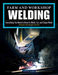
A comprehensive, visual handbook for welding in the farm, home workshop, school workshop, blacksmith shop, or auto shop. Almost anyone can weld, cut, or shape metal. That's the starting point for this supremely practical book which helps the beginner to improve and the intermediate operator to broaden their technique. Its detailed sections describe all the major types of welds before progressing into trickier methods. With this comprehensive guide, you'll understand everything you need to know, from arc, TIG, MIG, and gas welding to plasma cutting, soldering, welding plastic, and more. Beyond welding metals and plastics, advice extends into the wider workshop with chapters on drills, cutting threads, and basic blacksmithing. Filled with helpful visuals and photography, detailed explanations, expert suggestions, and step-by-step directions, author and experienced welding instructor Andrew Pearce also lays out common pitfalls and mistakes, and how to avoid or correct them. New, updated edition will include brand new chapters on general welding skills and understanding metals, expanded information on abrasives, and four new step-by-step projects and plans, including a steel table, fire pit, welding cart, and more.
Sie lesen das E-Book in den Legimi-Apps auf:
Seitenzahl: 435
Veröffentlichungsjahr: 2021
Das E-Book (TTS) können Sie hören im Abo „Legimi Premium” in Legimi-Apps auf:
Ähnliche


Frontispiece illustration: Hardfacing with MIG
Photographs by Andrew Pearce unless otherwise credited
Book layout by Liz Whatling
North American technical editor Brian T. Yarrison CWE, CWI
Marked photographs on pages 32, 33, and 112 courtesy of ESAB North America.
Additional photo credits: Shutterstock; Back cover, Valmedia, MIG Welding; Salivanchuk Semen, TIG Welding; Bogdan VASILESCU, Gas Welding; Interior, Aleksandar Malivuk, 4; Valmedia, 5 (MIG Welding); Salivanchuk Semen, 5 (TIG Welding); Bogdan VASILESCU, 5 Gas Welding and Cutting; Jack Frog, 119.
Projects featured in Bonus Section: DIY Welding Projects (pages 4, 119-134) are courtesy of Forney Industries and Hobart Welding Products, as noted. All photos and text are used with permission.
Copyright © 2012, 2021 Andrew Pearce and Fox Chapel Publishing Company, Inc., 903 Square Street, Mount Joy, PA 17552.
All rights reserved. No part of this publication may be reproduced, stored in a retrieval system, or transmitted, in any form or by any means, electronic, mechanical, photocopying, recording or otherwise, without prior permission of the copyright holder.
Farm and Workshop Welding, Third Revised Edition (2021) is a revised edition of Farm and Workshop
Welding (2012), published by Fox Chapel Publishing Company, Inc. Revisions include new text, photos, and bonus section with step by step projects.
Print ISBN 978-1-4971-0040-4
eISBN 9781607658641
The Cataloging-in-Publication Data is on file with the Library of Congress.
To learn more about the other great books from Fox Chapel Publishing, or to find a retailer near you, call toll-free 800-457-9112 or visit us at www.FoxChapelPublishing.com.
We are always looking for talented authors. To submit an idea, please send a brief inquiry to [email protected].
Contents
Introduction
Don’t Take Risks
First Things First
Any Old Iron? Metal Identification
Sections
1 Steels
2 Abrasives
3 Manual Metal Arc Welding
4 MIG/MIG Welding
5 Gas Welding and Cutting
6 TIG Welding
7 Plasma Cutting
Bonus Section: DIY Welding Projects
Welding Cart
Welded Steel Table
Metal Fire Pit
Deluxe Dog Waterer
8 Special Techniques: Cast Iron Welding
Pipe Welding
Hardfacing and Gouging
9 Soldering
10 Welding Plastics
11 Workshop Techniques: Taps and Dies
Drill Sharpening
12 Basic Blacksmithing
Appendices
What’s in a Name?
Heat Colors
Useful Conversions
BONUS SECTION
STEELS
Abrasives
Manual Metal Arc Welding
MIG/MIG Welding
Gas Welding and Cutting
TIG Welding
Plasma Cutting
Special Techniques
Soldering
Welding Plastics
Workshop Techniques
Basic Blacksmithing
Introduction
Almost anyone can weld. All that’s needed is basic hand/eye coordination, an idea of what’s going on, and a little guided practice. So far nobody has come up with a book that grabs the reader’s hands and says, “Do it like this!” And until someone does, pictures are worth a lot of words. So pictures are the heart of this book, forming a visual guide for beginners and a fault-finding service for improvers.
While not the last word on welding — other sources have a far better claim to that — the advice here is practical and aimed at the farm welder. The idea is to use the book for reference, dipping in and out to find snippets of info, the occasional hint, or maybe a way to get yourself out of a hole. It’s not for sitting down and reading at one hit, unless you have a particularly high boredom threshold.
So what’s coming? Twelve sections. First up is a run through types of steel and their uses. Abrasives, vital in pre-welding preparation and post-welding tidy-up, come next. The welding section opens with info on how to manually arc weld mild steel, detailing equipment, rod selection, plant setup, and work in various positions. As most people trip up on the same problems, there’s a look at common faults and ways to fix them. Section 4 deals with MIG welding, a very inviting but unexpectedly complex process. Then it’s the turn of the farmer’s increasingly neglected mates: gas cutting and welding.
With the basics sorted, the trickier business of TIG welding steps up. Potentially the most versatile of all techniques, this can really expand workshop capability. Hard facing, pipe welding, and ways to join cast iron come next, before going back to the simpler jobs of how to solder and to weld plastics. The latter is not often done on farms but can be a big money-saver.
Rounding off are sections on common workshop skills — drill sharpening, the use of taps and dies and basic blacksmithing. How come blacksmithing? Knowing how to shape metal is a great help when making and fixing farm equipment.
It’s pretty clear that reading can take you only so far. A good practical course is a fine way to improve, so check out your local college and training group. If that doesn’t appeal, then YouTube has a mix of good and not-so-good videos. For my money the best online resource is Jody Collier’s weldingtipsandtricks.com — check it out.
Should you wonder where the book’s content comes from, it’s based on the author’s contributions to Power Farming, Farmers Weekly, and Profi magazines. My grateful thanks go to ESAB’s Welding Process Superintendent Mick Andrews; to the Welding Institute’s ex-chief instructor Max Rughoobeer; to plastics specialist Dave Tucker; to St Gobian (abrasives); to Rudgwick Metals (steels), and to Sussex blacksmith Frank Dean, who sadly died in 2004. Everyone’s help was (and is) very much appreciated!
ANDREW PEARCE
Don’t Take Risks
Here is the line taken on safety throughout the book. Today’s duty of care requires that businesses and individuals both do, and are seen to do, the right thing regarding safe working practices.
So I don’t intend to ramble on endlessly about staying safe. Adults should have enough common sense not to need that, and ought to pack a sufficiently well-developed sense of responsibility to look after the well-being of themselves, others, children, and livestock.
If a risk or hazard exists that might not be obvious, I’ll try to point it out. Nevertheless, the responsibility to use good, sensible, and legal working practices rests entirely with the reader.
When welding, cutting, or grinding, use protective equipment — eye shields, fireproof clothing, proper footwear, and respiratory protection — as specified by industry guidelines. Advice on safe working is readily available: ask your welding equipment supplier, the equipment’s maker, or contact Occupational Safety and Health (OSHA). Be aware of the presence of children and livestock, and the possible risk to them from hot material, fumes, flying sparks, and ultraviolet radiation. Assess whether your skills are up to the fabrication or repair that you’re about to undertake, and think through the safety implications should it fail in service.
The bottom line is this: if you’re not 100% sure about how to do something and/or not 100% confident about the outcome, don’t do it.
First Things First
Just what is welding?
It’s the process of joining materials using heat. In fusion welding, joint components are heated until they melt together or are positively fused by pressure. Blacksmiths use heat and hammer blows, but here we’re more concerned with getting heat alone to do the work.
This heat will come from either an electric arc, a gas flame, or in the case of plastics, from a hot air gun. Filler is usually added to the joint from an electrode or separate rod. Non-fusion welding techniques like braze (or bronze) welding and soldering use heat too, but not enough to melt the metals that form the joint.
ANY OLD IRON?
Metal Identification
This book deals mainly with welding mild steels. But as not all bits found under the bench or rescued from the scrapheap will be made of it, we’ll start with different materials and their weldability. Although accurate identification of steel is a complex business, the main classes can be sorted out with a file, a grinder, and some basic ground rules. Section 1 expands on what follows, dealing specifically with steel grades and their application (see here).
Wrought iron isn’t very common now, but has been used extensively in farming for chains and hooks. It’s very low in carbon and malleable.
Mild steel is the common user-friendly stuff. It doesn’t harden (much) when heated and cooled, and is easy to bend and weld. Black mild steel is what you’d normally buy: as flat strip and other sections it comes with radiused edges and retains its coating of mill scale from hot-rolling.
Bright mild steel in flat form has square edges, is shiny, and is more accurately sized than mild steel. It’s made by cleaning and cold-rolling black mild steel, leaving the metal stronger but less ductile.
Silver steel looks like bright steel but is much harder. It contains chromium but, oddly, no silver. It’s usually sold in short lengths.
Black and bright mild steels are easily filed and give off long, light yellow sparks under an angle grinder. Both are readily weldable. Silver steel is not.
Adding more carbon to steel makes it harder, and logically enough produces the carbon steels (Table 1). As carbon level climbs, so does the end product’s hardness, brittleness, and difficulty of welding.
After forming to shape, carbon steels are often heat-treated (tempered) to boost their resilience. Welding heat can destroy the tempering effect, leaving the joint zone hard and brittle until it’s re-treated. Springs are a classic case.
The more carbon in a steel, the harder it is to file — and files themselves have very high carbon content.
So here’s a quick test. If an unknown material can’t be filed, it’s probably not weldable. The exception can be cast iron; see below. Grinding spark pattern also changes with carbon level. As it rises, the sparks get shorter, bush out closer to the grinding wheel, and may be darker yellow in color. If in doubt, compare sparks from the unknown item with those from a chunk of mild steel.
Although heat treatment will improve a carbon steel’s resilience, the really spectacular gains come from adding small quantities of exotic elements to produce alloy steels. All sorts of metals — nickel, tungsten, manganese, molybdenum, cobalt, vanadium — can spice the mix, and the end result is usually heat-treated to maximize its properties.
Alloy steels turn up wherever toughness, resilience, and corrosion resistance is needed. Typical applications are springs, gears, and transmission shafts. Stainless steel is a variant using chromium to beat corrosion, which for the metalworker is both good and bad news. Although stainless steel is slow to tarnish, that reluctance to oxidize means it can’t be gas-cut — but it can’t resist a plasma cutter. And while many stainless steels are non-magnetic and weldable, don’t weld if a magnet sticks to the bit you want to use; cracking is very likely.
Two jobs using a dissimilar steels electrode: a sash cramp’s cast iron endplate welded to the central mild steel beam for more rigidity
A slurry pump’s cast steel shear plate resurfaced back to near-original dimensions.
Table 1: Materials and their weldability
Material
Percentage carbon
Weldability
Typical use
Wrought iron
0.01–0.03
Good
Hooks, chains
Dead mild steel
0.1–0.125
Good
Wire, pressings
Mild steel
0.15–0.3
Good
General engineering
Medium carbon steel
0.3–0.5
May be made brittle
Structural steels, forgings, high tensile tube, some tools
High carbon steel
0.5–0.7
Will be made hard and brittle
Chisels, springs, hammers, railway lines
Very high carbon steel
0.9–2.0
Not weldable on farm
Files, razor blades, axes
Gray cast iron
2.0–4.0
Needs right method
Casting not subject to shock. Housings, pulleys, manifolds, etc.
White cast iron
2.0–4.0
Not weldable
Hard layer in wearing parts, camshafts
Malleable cast iron
2.0–4.0
Good with right method
Cutter bar fingers, coulter brackets, vice parts, clamps, etc.
Sorting an alloy from a carbon steel is largely a matter of application, though stainless stands out readily enough thanks to its satiny bright finish. Think about cost, too: a cheap hand tool is more likely to get its hardness from a tempered carbon steel than an expensive alloy one.
Castings can be recognized by their complex shapes, generally rough surface finish, and any raised surface lettering. But is the bit in your hand cast iron or cast steel? Application and a grinding test usually gives the answer.
Gray cast iron breaks very easily if bent or shocked to leave a grainy surface. But it stands compression loads very well, so turns up in machine beds, bearing housings, electric motor bodies, belt pulleys, engine blocks, manifolds, and such. Heat treating gray cast iron produces the much tougher malleable cast iron, which is close to mild steel in strength and ductility. Malleable cast is used where shock loads are high; in vice bodies, clamps, and pto shaft yokes. White cast iron is very hard and brittle, properties that are used when a cast part must resist wear. So for some soil-engaging parts, the molten iron is chilled in specific areas while in the mold, forming an outer layer of hard while cast.
Cast steels stand much harder service, being tougher than cast irons and capable of being heat treated to boost their resilience. Cast steels turn up where a durable, complex shape is called for.
Telling the two apart is pretty simple. The quickest way is to grind them: cast irons give off unmistakable dull red/orange red sparks that don’t sparkle and fade very close to the wheel, while cast steel sparkles clear yellow like mild — though the sparks are closer to the wheel and more bushy.
The hammer test is another decider. Tap cast steel and it rings, while cast iron just makes a dull clunk. Other differences? Cast iron fractures to leave a very characteristic coarse, grainy, gray surface — break a bit to see — and if you drill or file it, the swarf is powdery. Cast steel produces silvery filings.
When you start to file or machine cast iron, it may seem very tough. This is down to a hard skin of white cast iron, formed on the surface where molten iron contacted cold sand in the mold. Break through this skin and the gray cast underneath files, drills, and machines very easily. Cast steels don’t have this hard shell.
Iron and Steels: Carbon Contents and Uses
Blast furnaces make pig iron, which is high in carbon and impurities. Refining produces the following series of materials, with hardness and brittleness increasing as carbon content goes up.
Steels in the lower reaches of the carbon league are weldable on the farm. Ditto for those in the middle, though they need greater care in rod selection, joint preparation, and subsequent cooling. High carbon steels are unweldable by normal methods. Adding dashes of other elements to carbon steels gives a wide range of tougher alloy steels — see Section 2.
What Should You Weld?
Everything depends on the material involved and its application. Making 100% reliable joints in anything other than mild steel needs the right electrode and technique, and may call for specific procedures before and after welding to retain the metal’s properties.
There is only one rule. Don’t weld any safety-related component unless you’re completely sure about its makeup and any heat treatment it may have had. If the part must be repaired rather than replaced, take it to a specialist.
What are the options when safety is not at stake, or 100% reliability is not essential? Here a “dissimilar steels” electrode may be the answer.
Although metallurgists rightly stress the importance of matching rod and material, these jack-of-all-trades rods often get round material mismatches. If you’re faced with joining carbon or alloy steel:
• Choose a rod that matches the most awkward of the metals to be joined.
• Preheat. A gas flame heats moderatesized parts. Move it around to keep heat input even.
• Use the minimum current needed for fusion, and keep run number low.
After welding, let the work cool very slowly. Lay it on warmed firebricks or on dry sand, and cover it to keep off drafts. Don’t put just-welded work on cold surfaces and never, ever, quenchcool. Even mild steel can harden a little if its carbon content is toward the upper limit, so where strength really matters, don’t quench a mild steel repair in water.
Medium carbon steels can be stressrelived after welding by heating the joint area to very dull red and then cooling slowly (see distortion control).
Welding cast iron is covered in Section 4. Preheating gray castings helps a great deal, and low welding heat input followed by slow post-weld cooling are always necessary. Even then, success with cast iron is never completely certain thanks to the material’s tendency to crack as it cools. It’s important to know which cast iron you’re dealing with: malleable cast will cool to brittleness if arc welded, so lowertemperature bronze welding is better. Gray cast will turn to the brittle white form if cooled too quickly.
Section 1
Steels
Mild steel is usually the first choice for making or fixing stuff in the farm workshop. And why not? It’s easy to get, easy to work, relatively cheap, tolerant of heat/vibration, reluctant to harden, straightforward to weld, and easy to machine. In other words, a good and natural choice for most jobs. Yet it’s not necessarily the best option. Other steels have properties that suit them better to specific applications — and by choosing material(s) with an eye to likely loads and service conditions, the final product of your efforts will most likely be stronger and more durable. An example: you need to change a pivot pin on an old bit of kit but the part is no longer listed. You could knock up a new one from mild steel bar, but depending on the load, what the pin runs in, and the lubrication arrangements, wear could be very rapid. But if you make the pin from a more suitable steel, it will last for years.
Qualified engineers know their steels and how/where to exploit them, with or without an accountant’s eye to cost. For the rest of us it’s handy to highlight some the many grades on offer and see their advantages and constraints. Before we kick off, a few points:
• Engineering steels are classified separately from structural steels.
• Engineering steels come in familiar sections — round, flat, bar, square, and hexagon — and include higher-carbon and alloy forms.
Structural steels are relatively low in carbon and come as beams and columns (RSJs), as well as in channel, flat, round, square, sheet (including galvanized), mesh, and finally tube (round and box, seamed or seamless).
• Engineering steels come in various finishes. The most common are black (hot-formed with residual mill scale) and bright (cold-formed, shiny finish). Ground bar steel is bright and finished to close tolerances, so suits shafts. Structural steels are black-finished.
1.1. There’s plenty of choice of steels and non-ferrous metals from a good stockholder.
1.2. Bright steel is cold-drawn to size, which produces a shiny finish. This is EN19T.
1.3. Continuously welded box or tube has a seam. This projects inwards, making life difficult when you’re trying to get one section to slide freely inside another.
1.4. Seamless box or tube has no internal weld projection and is more uniform in size, so is stronger than the equivalent welded section. Cold-drawn seamless (CDS) tube comes in different grades; some can readily be bent, others are more rigid.
1.5. Black steel, whether engineering or structural, is hot-formed and carries some mill scale.
1.6. Steel comes in standard lengths and is usually color-coded. But as there is no standard code, individual mills and retailers can (and do) use their own scheme.
1.7. Key steel is a medium-carbon, bright material finished to a wide range of sizes. Depending on the application, substituting a softer mild steel version of a damaged key may cause early failure.
• The supplier will be your friend if you list the planned use, type, section, size, length, and finish of material before calling. This saves time and is a basis for discussion.
• Various standards and grading systems are used to classify engineering steels. In this chapter the older BS970 and the newer BS 1991 reference numbers are used, as these are widely recognized in the UK. Structural steel BS EN grades are prefaced by “S.”
• Steel may be color-coded for identification, but the system depends on the mill and/or supplier. There is no UK standard.
• Carbon content, alloying element percentage, and tensile strength figures vary slightly between suppliers.
• The following examples are either carbon or alloy steels. Stainless steels, tool steels, and non-ferrous metals have their own grades.
• On here, tensile strength is given as both maximum and yield point strength values.
A caution before going on. While mild steel is very tolerant of the usual forming and joining processes, other steels may not be. Heat, either used to bend the material or from welding, can substantially alter their properties. Cold bending may make the material brittle; heating can soften or harden it, depending on cooling; welding may need specific consumables and/or techniques. Before buying, sort out exactly what you want to do with (and to) the steel. Then discuss which material will be most suited to the application with a good supplier. Take professional advice if you’re not 100% sure. That way the result will be safer and more cost-effective.
Carbon Steels
Steel is an alloy (a mix) of iron and other elements. Carbon steels are ranked according to their carbon content, though this is not the only extra element in the mix. Carbon content typically runs from 0.15% max to 2.0% — definitions vary — with 0.5% usually seen as the upper limit for medium carbon material, though that definition too can be hazy. The more carbon in the steel, the harder and tougher it can be made by heat treatment but the trickier it is to weld. Mild steels (and there’s more than one) contains up to 0.25% carbon. Here are some common carbon steels in ascending content order.
BS 970 EN1A
Equivalent BS 1991 grade: 230M07
Carbon content: 0.15% maximum
Max/yield tensile strength: 360/ 251 N/mm2
Sold as black or bright in round, square, flat, hexagon.
A low carbon, free-cutting mild engineering steel for machining in manual or automatic lathes. Swarf forms small chips. Not readily hardened.
BS 970 EN3A
Equivalent BS 1991: 270M20
Carbon content: 0.16%–0.24%
Max/yield tensile strength: 400-560/ 300-440 N/mm2
Sold as black or bright in round, square, flat, hexagon, angle; also ground steel bar
The most common of the low-carbon mild engineering steels, used for general fabrication. Easy to bend and readily welded with MIG, MMA, TIG, or gas. Not good in high-strength applications. Can be case hardened if heated and quenchcooled. May then be tempered, but EN8 or EN9 are preferable for this.
BS 970 EN8
Equivalent BS 1991: 080M40
Carbon content: 0.35%–0.45%
Max/yield tensile strength: 700-850/ 465 N/mm2
Sold as black or bright as round, square, flat and ground bar. Price premium roughly 10% over mild steels.
A medium carbon, medium tensile strength machinable engineering steel. Readily hardened and tempered to improve wear resistance. Use where mild steel won’t do but where an expensive alloy steel is not justified: axles, some pins, studs, shafts. Watch out for hard, brittle face potentially left by flame cutting. Weld with MIG or low hydrogen MMA rods. Preheat thick sections to minimize change of cracking.
BS 970 EN9
Equivalent BS 1991: 070M55
Carbon content: 0.50%–0.60%
Max/yield tensile strength: 600-700/ 310-355 N/mm2
Sold as round, square, flat, plate.
More carbon than EN8 but still a medium carbon engineering steel. Readily heat treated, resists wear well. Often used for sprockets, gears, and cams. Pre/post heat and specific consumables needed when welding.
BS 970 EN43 Spring steel
Equivalent BS 199: 080A57
Carbon content: 0.45%-0.60%
Max/yield tensile strength: 380/ 210 N/mm2
Sold as bar and plate
A carbon steel with manganese and silicon for oil hardening and tempering. Used for springs and hand tools.
BS EN 10025: S275
Carbon content: 0.25% max
Min yield tensile strength: 275 N/mm2
Sold as beams, columns, flats, tubes, etc.
Use: A low-carbon structural manganese steel for general fabrication and building work. Easily welded by common processes. Name reflects its minimum yield strength — 275 N/mm2.
BS EN 10025: S355
Carbon content: 0.20% max
Min tensile strength: 355 N/mm2
Sold as beams, columns, flats, tubes, etc.
A low-carbon structural manganese steel with slightly different composition than S275. Easily welded by common processes. Better impact resistance than S275, easily machined, better in demanding environments. Name again reflects minimum yield strength — 355 N/mm2.
BS46 Key steel
Carbon content: 0.40%–0.45%
Max tensile strength: 500-700 N/mm2
Sold as bright squares and flats
Medium carbon steel drawn to specific tolerances in metric and imperial sizes. Harder than mild steel, used for square, taper, plain, half moon and gib head keys.
Alloy Steels
Alloy steels result from adding various proportions of extra elements — typically manganese, chromium, nickel, boron, vanadium, and molybdenum — to medium carbon steels. The result is a wide range of engineering metals that are intrinsically tougher and more resilient than carbon steels, and whose properties (including resistance to impact, wear, and corrosion) can be extended by heat treatment. For example, case hardening or nitriding produces a material with a hard exterior and resilient core. Alloy steels are relatively expensive, vary in machinability, need consideration and care when welding and come in only a few sections, limiting their use in the farm workshop. Components made from them are often machined, heat treated, and finally ground to exact size. Unless you really must have properties that only an alloy steel can bring, then a medium carbon steel like EN8 — perhaps heat treated by a specialist to match the application — is often enough.
BS 970 EN16T
Equivalent BS 1991: 605M36
Carbon 0.36%, Mn 0.45%, Mo 0.20%, Cr 1.00%, Ni 1.30%, Si 0.10% (min values)
Max/yield tensile strength: 850-1,000/ 680 N/mm2
Supplied usually heat treated as round, ground bar, hexagon, black or bright.
A ductile, shock resistant, low alloy manganese-molybdenum engineering steel. Machinable. Usually used for high strength, resilient shafts and axles; also bolts, cams etc.
BS 970 EN24T
Equivalent BS 1991: 817M40T
Carbon 0.36%, Mn 0.45%, Mo 0.20%, Cr 1.00%, Ni 1.30%, Si 0.10% (min values)
Max/yield tensile strength: 850-1,000/ 650 N/mm2
Sold as round, square or flat, black or bright.
Widely used nickel-chrome-moly engineering steel combining strength, wear resistance, shock resistance and ductility. Can be heated to extend its properties in several directions. Used for driveshafts, shafts, gears, cams, etc.
BS 970 EN45 spring steel
Equivalent BS 1991: 250A53
Carbon 0.5%, Mn 0.7%, Si 1.50%, p 0.05% max, S 0.05% max
Max/yield tensile strength: 1,500/ 1,100 N/mm2
Supplied as round and flat.
Common in vehicle applications. Very resilient spring characteristics once oil hardened and tempered. Used for the making and repair of leaf, coil and flat springs.
The above examples cover the popular ground. When you aren’t sure which steel is right for a given job, the best thing is to speak to a competent supplier. With the material sorted out, the stockholder should be able to point you (if necessary) to advice on welding process(es) and/or heat treatment. Take that line with your steel choice and you’ll end up with a better result — not to mention a potentially cheaper and safer one — than if you just use whatever you can find and hope it will be OK.
Section 2
Abrasives
Whenever you set out to weld, braze, or solder, cleaning the work is number one priority. And with steel, the easiest, fastest, and most effective route to get there is via one or more abrasives. There’s a wide choice out there, in form (cloths, discs, flap wheels, stones) and in method of using them, from manual work to power tools. Once the latter swing into play they bring a risk element, too — so for starters, here’s something to remember: angle grinders and their bench-mounted brethren can do you serious harm if not treated right.
Given that encouragement, we’ll sort out safety first. Mostly we use grinders on steel and on stone without a second thought, but ponder this. Spinning without load, the outer edge of a typical angle grinder disc flies by at 80m/s. That doesn’t sound like much. Yet 80m/s is 290km/hr, or a scorching 180mph. And if you’re in any doubt over what can happen when a disc bursts, just search the web for “angle grinder accident.” So here’s how to avoid that.
A good-quality abrasive wheel or disc is made and tested to very strict standards and is extremely unlikely to give the user any grief — but only when the wheel is chosen, mounted, and used properly. Humans being humans, accidents tend to start in the last part of that.
We’re dealing here with bonded wheels. That is, types where the abrasive is held in a solid matrix or binder. The nature of the binder and the type of construction then splits bonded wheels into two broad classes — resinoid grinding/cutting wheels (or discs) used mainly in handheld tools, and vitrified wheels used in bench grinders. The two classes have very different properties and need very different treatment. There are also flap wheels, made from overlapping abrasive strips — more on those later.
A word on quality and its impact on safety and service life. In Europe, all bonded wheels must conform to EN12413. Among many other things, this requires each wheel to show the relevant standard and to carry vital information on its maximum permitted peripheral (outer edge) speed and rpm. Good-quality wheels always carry this info, along with pictograms laying out the wheel’s application(s), recommended safety equipment, and markings that allow the wheels’ origin to be traced. Look for these, plus the oSa (Organisation for Safety of Abrasives) symbol — see “Wheel markings” for more. Lower-quality wheels are usually cheaper and may not have all of the above. They can also be much more variable in quality and will probably have a shorter service life. Abrasive flap wheels must conform to a different standard — EN13743.
For material removal and cutting metal or stone, thin resinoid-bonded wheels — usually angle grinder discs on the farm — are the thing. Ranging in thickness from 1/32" to ⅜" (1mm to 10mm), they hold abrasive grit in a resin matrix, and always feature fiberglass mat reinforcement. The resin and mat bring toughness, allow high-rpm operation and in thinner discs, allow significant flexibility. Resinoid wheels are built up from layers of bond and mesh, pressed in a mold and cured at relatively low temperatures; a metal center disc usually provides an accurate mounting surface. For typical farmsized 4", 4½", 5", 7", and 9" (100mm, 115mm, 125mm, 180mm, and 230mm) angle grinders, the maximum peripheral wheel speed is 80m/s, regardless of wheel diameter.
Vitrified bonded wheels are quite different. Designed for use on bench grinders, they use a mineral or synthetic material to hold the abrasive. Fired at very high temperature, this turns into a hard, brittle, and glass-like bond. As there is no separate reinforcement, vitrified wheels are more prone to shock damage than resinoid wheels and can’t stand high rpm. So their maximum peripheral speed is lower at 35m/sec-50m/s.
Wheel care and machine use comes down to six golden rules. Stick by these, add a healthy dose of respect for the equipment and you’ll be fine.
The rules:
• Match the wheel to the work.
• Be sure that the machine can’t physically spin the wheel faster than its maximum allowable peripheral speed or rpm (see “Stumped for speed”).
• Mount the wheel properly.
• See that machine guards are in place and secure.
• Keep the wheel’s design in mind while using the tool — for example, don’t grind with a cutting disc.
• Wear the right protection for eyes, hands, ears, and lungs.
A full safety code can be found at www.fepa-abrasives.org.
Types Explored 1: Resinoid Cutting and Grinding Wheels
For safety and good service life, it’s essential that discs for grinding and cutting are intact, spin at the right speed, and be mounted securely. Beyond that, how you present the wheel to the work has a big impact on material removal speed as well as safety.
And of course the machine’s guard must be fitted. Some of the nastiest accidents happen after a guard has been taken off, usually for better access to a corner or to fit the wrong size of wheel. Such daftness aside, changing wheels and using a handheld grinder comes down to common sense, though not everything is obvious, as the pictures below show.
2.1a. and b. See that the machine you use can’t spin the disc faster than its maximum allowed speed. Find the disc’s max rpm (2.1a) or calculate it if it’s not visible — the box “Stumped for speed” shows how. Here it’s 6,650rpm. Then find the grinder’s max spindle rpm (2.1b); in this case 6,600rpm. As that’s 50rpm lower the wheel’s limit, the pairing is safe to use. Last, check out the disc for cracks and/or missing bits before you mount it, and junk it if you find either.
2.2a. and b. Not everyone notices that the upper spindle flange on angle grinders is generally reversible. The side with a raised inner rim (2.2a) is for use with grinding discs. Fit it so the raised section locates and centers the disc. Use the flat and/or recessed side (2.2b) with cutting discs. Get the flange the wrong way round with a cutting disc and the slim raised rim limits clamping force; the disc can then slip and may stall in the cut, with a risk of damage to you and it if you just yank it out with the tool under power.
2.3. Discs with a depressed center must be fitted with the low section toward the machine body, as the depression adds mechanical strength. Don’t fit a disc the wrong way up even if the tool allows — it’s not designed to run that way.
2.4. Switch off the grinder at the mains and unplug it before changing wheels. Go easy when tightening the flange; just nip it up enough to grip the wheel, no more, then spindle rotation will build on that. Over-tightening means struggle when you come to change discs.
Wheel Markings
A good-quality disc carries all the info you need to suit it to the job, match it to the machine, and use it safely. Pictured is a 9” (230mm) angle grinder cutting disc that, like all good-quality products, has info permanently etched in during manufacture rather than added as a sticky label. First thing to look for is the EN12143 mark, which on this wheel is shared with a unique identifying barcode (A). Next find the wheel’s max permissible speed, here given in m/s and rpm (B). Also here are the wheel’s dimensions in mm and inches, plus a code — A46T-BF41. Use Table 2.1 to crack these codes: this one breaks down as follows:
• A = abrasive type (aluminum oxide)
• 46 = grit size (46 per linear inch)
• T = grit hardness (hard)
• BF = bond type (Bakelite/glass fiber reinforced)
• 41 = shape specification (flat cutting-off wheel)
Item C in the picture is the range of applications the disc is designed for. Also obvious should be a selection of symbols (D). These point to the safety equipment the user should wear and show specific details, for example that the wheel contains no iron, sulfur, or chlorine (so won’t contaminate stainless steel) and that it must not be used for grinding. Item E is the oSa symbol, confirming that the makers belongs to the Organisation for Safety of Abrasives; this guarantees that the product meets at least EN 12413.
Finally, look at the center ring. This should show the wheel’s validity date. The organic bonding in resinoid wheels degrades over time, so a three-year shelf life is usually recommended. The ring should be stamped with the use-by year, along with a two-digit code showing which quarter it was made in. In this case, the expiration date was the third quarter of 2012.
Wheel markings
2.5a. and b. An angle grinder’s guard can — and should — be rotated to suit the job. In 2.5a it’s set for cutting: the lower edges of the guard line up with the grinder’s body. Picture 2.5b shows the guard turned through 90° for grinding. The important thing is that the guard always sits fully between the wheel and you.
2.6. Run grinding discs at 30°–45° to the work. A relatively small contact patch then removes material fast. Shallower angles spread the wheel’s pressure and slow down material removal. Low angles also thin the edge of the wheel, which often then loses small chunks and becomes ragged — usually as wheel diameter decreases.
2.7. Flap discs need to run at a shallower 10°–15° angle to put maximum abrasive in contact with the work.
2.8. Cutting wheels are thin, partly to concentrate pressure on the working edge and partly to minimize cut width. Although reinforced, these wheels are definitely not designed to take side loads — it’s very easy to snap a 4½" x1/32" (115mm x 1mm) item with just finger pressure. Bring this picture to mind every time you’re tempted to grind with a cutting disc.
2.9. It follows from 7 that a cutting disc should be used vertical to the work, as shown. Load then passes safely up through the disc. Side loads can fracture a disc wheel or tear out the center, so trying to cut in anything other than straight lines is likely to bring grief.
Flap Discs
Resinoid discs are the roughnecks of the angle-grinding world. We’ve seen that the grinding variety is best used at a relatively steep 30°–45° angle to the work, which concentrates your downward pressure to make the abrasive cut. Resinoid discs can handle any material apart from aluminum and other soft metals that clog the abrasive, but they do leave an uneven finish. On heavy jobs like removing old weld metal, scouring out rust pits, or cleaning up gas-cut edges, that’s not a problem.
Resinoid discs cover most bases. Goodquality ones aren’t expensive and offer sensible service life. On top of that most farms work predominantly with steel, and getting a newly welded fabrication or repair out of the door usually takes priority over the job’s appearance — but sometimes you need something a little more genteel. That’s where flap wheels step in.
Pictures show items from Norton’s range, but other brands have comparable products. Expect to pay a premium for high-end items, but expect the reward of better performance and longer life.
Where can you use flap discs? At the three stages stage of repair and fabrication — surface prep, metal removal, and cosmetic finishing.
1. Surface preparation. Here the broad class of non-woven discs is good at getting shot of paint, mill scale and light rust, along with platings like zinc galvanizing and other corrosion-preventers. Rather than holding an abrasive in a rigid and reinforced resin, non-woven discs put it in a web of synthetic fibers and hold it with a dry smear-resistant adhesive. Various types and grades of abrasive can be held in the web, which is supported by a thin, consumable backing plate. By adjusting the type of abrasive and its grit size, makers generate a family of non-woven discs able to grind at one extreme and polish at the other. Non-woven discs do a fine job removing light rust, paint, scale, and other weld contaminants from metal, plus they can strip unwanted crud or paint from cement or even wood. Some types can handle relatively heavy grinding work as well, depending on the pressure applied, and are can even work on rough, snaggy material. But naturally around such surfaces, the softer the disc, the more care that you need to take to avoid damaging it.
Stumped for Speed?
How do you find the safe maximum rpm that a wheel can be spun at, if all you can see is its max peripheral speed? A little recreational math is called for:
So for a wheel of 230mm (9in) diameter and a max peripheral speed of 80 m/sec:
Which rearranges to
So in this example, safe maximum rpm = 6,642.
A non-woven disc is typically ½" (12mm) deep, that is, front face-to-back face. When the front face is used at a shallow 15°–20° angle, its generous area lets you cover a lot of ground quickly. Or where access allows, you can use the outer rim in the angle of a joint for a final clean before welding. Negatives compared to resinoid discs are more-orless sensitivity to sharp edges, a shorter service life, and higher cost/life ratio.
2. Metal removal. Usually this involves tidying-up joint edges before welding and if necessary, beveling them. The ability to grind a decent bevel also comes in handy when sharpening hedge cutter flails and mower blades. Resinoid discs will do the job, but producing a flat, uniform bevel is a bit of a lottery. Instead, a flap disc produces a much better finish and is more controllable. Flap discs are made from overlapped strips of abrasive cloth anchored to (and supported by) an angled fiberglass backing plate. The plate’s angle is a shallow 15°, which automatically suggests the disc should be used at a similar low angle; this in turn produces a big footprint on the work and lets the flap disc deliver a flat, uniform finish. Beyond grinding bevels, flap discs find plenty of use in blending or tidying metal, de-burring edges and holes, or on any other work where their forgiving, contour-following nature can be exploited. The downsides? You can’t grind with a flap disc’s edge, service life is shorter than for resinoid types, the per-item cost is higher, and the flat footprint makes cleaning out rust pits more difficult. Horses for courses, as they say.
3. Finishing. Where time allows it’s always satisfying to bless a job with a good cosmetic finish. Not a mirror polish (though that’s possible) but knocking off weld spatter and blending-in bead edges, then perhaps stripping off all old coatings on repaired parts before repainting. Here a flap wheel and nonwoven discs can work as a team: a flap wheel for initial metal removal and a non-woven one(s) for final blending and stripping. This suggests each has its own exclusive territory, though in reality their applications overlap. In common their big contact area means fast work, and as ever with abrasives, smaller grits deliver a finer finish — see “Graded Grains.”
Graded Grains
By juggling the abrasive and bond, resinoid and vitrified wheels are produced. Within these the bond strength, the abrasive type and the grit size suits the disc or wheel to different work.
Resinoid cutting and grinding wheels use several different abrasives. Two are very common and suited to farming applications:
• Aluminum oxide (alumina). A general-purpose abrasive for grinding and cutting metals only. Will not cut stone. Naturally occurring or synthesized.
• Silicon carbide. Recommend for stone but will also cut most steels. Sharper grains than aluminum oxide.
With either, grit size choice is narrow and not too important in general farm work.
Good-quality resinoid wheels carry a hardness grade letter — see Table 2.1. Grades show the relative holding power of the bond: soft grades have earlier letters in the alphabet and release abrasive earlier, so exposing fresh sharp grains.
Vitrified wheels give a wider choice of abrasive. The most common are:
• Aluminum oxide. Color white or brown; general-purpose use.
• Silicone carbide. Color green. For harder materials including high-speed steels and tungsten carbide tooling, nonferrous metals and cast iron.
• Ceramic. Color blue. For hardto-grind materials. A long-lasting high-performance material.
• Alumina-zirconia. Comes from the fusion of aluminum dioxide and zirconium dioxide, toughening the alumina. Extremely hard grains with high resistance to dulling.
Grit size choice is also wider in vitrified wheels, running from 24 (coarse) to 120 (fine). Which to buy depends on the application: coarse grits give faster material removal, finer grits give a finer finish. One option is to mount coarseand fine-grit wheels on one bench grinder, say a 46 grit on one side and a 60 grit on the other. Alternatively, fit an aluminum oxide wheel and a silicon carbine one so the one grinder can handle a range of materials.
In general, softer-bond wheels are best for hard materials like drills, lathe tools, chisels, and so on, along with large contact areas and rapid material removal. Harder grades are more general-purpose and are better for softer materials, on small contact areas and where longer service life is important. Medium-hardness wheels suit most farming applications.
The Safe Angle
Flap- and non-woven discs are slightly less threatening than the resinoid variety. Although spun at the same rpm by the grinder, fragments from a non-woven disc generally have less mass and so lower impact energy. That’s not to say that the basic rules of angle grinder use can be ignored, though, so . . .
• Mount the disc securely using the right flanges.
• Use the grinder’s guard, set so it’s completely between the disc and you.
• Wear eye protection and a mask that protects against abrasive/matrix/material dust.
Practicalities
For best performance, 4½” (115mm) flap or non-woven discs with ceramicbased abrasive should be used with a 1,000W–1,500W angle grinder. Why? Lower-powered machines won’t necessarily put enough energy into the abrasive to fracture its grains (a process necessary to create fresh cutting edges) so the disc can’t perform as intended. Other considerations:
• As non-woven discs are substantially thicker than a conventional dished item, you may need to add a cranked section to the grinder’s pin spanner so it can reach the spindle flange.
• Disc depth means that a quick-release guard can make it easier to change non-woven discs
• Non-woven and flap discs have less dense, more flexible base material than resinoid ones. So they follow contours better, feel less harsh to use and generate less vibration — but they do shed many tiny flecks of matrix as they wear, so post-work cleanup needs to be thorough.
How Does an Abrasive Wheel Cut?
The way discs and wheels cut or grind is pretty nifty. Abrasive grains — which today are often synthetic — are held in the wheel’s bonding matrix. Each grain is like a small chisel, able to slice off slivers of material. Like any cutting tool, a grain loses its edge after a while so starts to rub more than it cuts, so friction goes up. The grain’s temperature climbs until it melts the holding matrix, at which point the spent grit is flung free and fresh, sharp abrasive is exposed. Clever, eh?
Can I . . .
. . . grind on the side of a vitrified wheel? Tempting, especially if the face of the wheel is not flat and you need to sharpen a drill or a lathe tool on it. But it’s risky: conventional flat vitrified wheels are not designed to stand side loads and can shatter. Instead, dress the wheel’s proper working face flat and use that (see photos 2.16a, 2.16b, 2.17).
. . . use a worn-down 9” (230mm) disc in a smaller angle grinder? Another temptation to avoid! Spindle speeds on smaller grinders must be relatively high to produce the right peripheral speed on a small-diameter wheel. So there is a real risk of over-speeding a worn larger 9” (230mm) wheel, even though its diameter is much smaller than when it was new.
Vitrified Wheels
To round off this section we’ll gallop through the third major type of abrasive wheel — those used with bench grinders and low-low-powered craft tools.
As we said earlier, vitrified wheels hold their abrasive in a mineral or synthetic material. During manufacture the wheel is fired in a kiln at very high temperature, which turns the material into a hard, brittle and glass-like bond. This leaves vitrified wheels more prone to shock damage than resinoid discs discussed last time, and more rpm-sensitive. Their relative fragility means you must take particular care in mounting them and in use, and key points are covered in pictures.
It’s essential to make sure that the grinder can’t spin the wheel(s) too fast. Both the wheel and grinder should have info on their respective speeds (peripheral/rpm on the wheel, spindle max rpm on the grinder), and as before the grinder must spin more slowly than the wheel’s allowable maximum. If you can’t be sure that the wheel will be working at a safe speed, don’t mount it!
And it’s doubly important to check a vitrified wheel’s physical integrity before you fit it. Look for cracks or damage, and do a ring test. The highest risk of bursting or fragmentation comes each time a wheel accelerates from rest, so once a new wheel is mounted, stand clear on start-up and run it for a minute or two to make sure all is OK. You should treat a vitrified wheel with particular care when grinding; make contact with it gently and let the wheel do the work. Don’t force material in, and keep the work down on the grinder’s tool rest.
Again stick by the six rules:
1. Match the wheel to the job.
2. Be sure that the machine can’t spin the wheel faster than its maximum allowable peripheral speed or rpm.
3. Mount the wheel properly.
4. See that machine guards are in place and secure.
5. Respect the wheel’s design capability in use.
6. Wear personal protection for eyes, hands, ears, and lungs.
2.10a. and b. A bench machine’s info plate should show spindle rpm (2.10a); measure it using a tacho if not. Likewise the wheel should carry its maximum peripheral speed and/or rpm (2.10b). If the wheel won’t be spun faster than its design speed and is physically in good shape (see 2.11), then go ahead. If you can’t find the wheel’s maximum speed, DON’T USE IT!
2.11. Vitrified wheels can stress-crack if not stored and handled with care. So keep them dry, laid flat or stood on edge. Surprisingly they are porous and will take up water, which can unbalance the wheel and increase the risk of bursting. So before fitting any vitrified wheel, check it visually for water stains, cracks and chipping. Then support it on a finger and tap it with a length of hardwood, not a metal tool. A good wheel will ring, a damaged one will produce a dull clunk. The ringing won’t be like a bell but you’ll recognize it.
2.12. Bench grinder wheels commonly have a center bore of 1¼" (32mm or 31.75mm). This is much bigger than the spindle of smaller machines, so bushes are needed to match one to the other. Usually plastic, these are slightly tapered, come in pairs and are readily available. It’s essential that the bushes are a snug fit in the wheel. Don’t use Imperial ones in metric wheels as they are slightly too small; the resulting slack lets the wheel run eccentrically, greatly increasing the risk of bursting. Metric bushes are OK in Imperial wheels as their taper accommodates the size difference. Also make sure that the wheel’s two soft paper blotters are in place. These cushion the wheel against surface roughness, which will otherwise act as stress raisers (see photo 2.13).
2.13. Vitrified wheels are sensitive to point pressure. This can be the source of a dangerous stress fracture in use. Before mounting a wheel, check the spindle and both flanges for grit or metal fragments that, if trapped against the wheel, will concentrate stress (arrows).
2.14. Unplug the grinder before working on it. Tighten the spindle nut just enough to secure the wheel snugly: it will selftighten in use.
2.15a. and b. Plenty of accidents come from tool rests that are not set close enough to the wheel. The gap in pic 2.15a is too big — material can be pulled into it, risking damage to the work, wheel, and operator. Set a minimum clearance gap to a new wheel, then as the wheel wears down keep adjusting the tool rest to maintain the gap at less than ⅛" (3mm) (2.15b). If you can, set the tool rest on (or a little below) the spindle centerline to minimize the tendency of the work to pull into the clearance gap. When using a wire brush in place of a wheel, it can be safer to remove the tool rest.
2.16. Should a wheel burst, it will cause minimum havoc if the guards enclose as much of the flying material as possible (A). Use the grinder’s own eye shield (B). If that’s too scratched, switch to safety glasses or goggles. Grinding without eye protection is only for fools.


