Erhalten Sie Zugang zu diesem und mehr als 300000 Büchern ab EUR 5,99 monatlich.
- Herausgeber: The Crowood Press
- Kategorie: Lebensstil
- Sprache: Englisch
- Veröffentlichungsjahr: 2005
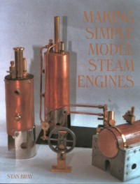
In this book long-time model maker Stan Bray describes the construction of a range of uncomplicated miniature steam engines, for construction by the model engineer.
Sie lesen das E-Book in den Legimi-Apps auf:
Seitenzahl: 242
Das E-Book (TTS) können Sie hören im Abo „Legimi Premium” in Legimi-Apps auf:
Ähnliche


First published in 2005 byThe Crowood Press LtdRamsbury, MarlboroughWiltshire SN8 2HR
www.crowood.com
This impression 2021
This e-book first published in 2024
© Stan Bray 2005
All rights reserved. This e-book is copyright material and must not be copied, reproduced, transferred, distributed, leased, licensed or publicly performed or used in any way except as specifically permitted in writing by the publishers, as allowed under the terms and conditions under which it was purchased or as strictly permitted by applicable copyright law. Any unauthorised distribution or use of this text may be a direct infringement of the author’s and publisher’s rights, and those responsible may be liable in law accordingly.
British Library Cataloguing-in-Publication Data
A catalogue record for this book is available from the British Library.
ISBN 978 0 7198 4357 0
Disclaimer
Safety is of the utmost importance in every aspect of metalworking. When using tools, always follow closely the manufacturer’s recommended procedures. However, the author and publisher cannot accept responsibility for any accident or injury caused by following the advice given in this book.
Contents
PART ONE: INTRODUCTION
Getting Started
Drawing Conventions
1 General Construction Notes
PART TWO: THE ENGINES
2 Hero’s Engine
3 Simple Sam
4 Tin Can Tommy
5 Slim Sam
6 Millie, a Mill-Type Engine
7 Invar, an Inverted Vertical Engine
8 Douglas, a Double-Acting Engine
9 Twinky, a Twin-Cylinder Engine
10 Victor, the Vee-Twin
11 Clarence, a Clapper Engine
PART THREE: BOILERS
12 Basic Boiler Construction
13 Boiler Fittings
14 Boiler Number One: Pot Boiler
15 Boiler Number Two: Basic Vertical Boiler
16 Horizontal Boiler with Water Tubes
17 Vertical Boiler with Flues
18 Boiler Number Five: Double-Barrelled Boiler
19 Supports and Burners
PART FOUR: FINALE
20 Vertical Boilered Locomotive
Glossary
Index
PART ONE
INTRODUCTION
Getting Started
Steam engines led the industrial revolution; their introduction into industry changed the way goods are produced, and therefore subsequently the way in which human beings live. Some will say this is a pity, as life now has a far quicker pace than it did before the industrial revolution, but others feel that the advantages of mechanization far outweigh the many disadvantages that it brought with it. Of course generally the steam engine as a means of power has long been superseded by the use of oilbased fuels and even nuclear power. Even so, much of industry is still powered by steam except that these days it tends to be used in turbines rather than the old-fashioned reciprocating engine.
Basically machines operated by steam are simple: it is a case of boiling water, collecting the steam that is generated in the process, and putting it in a closed cylinder so that it will operate a piston. The trick in being successful is the manner in which the steam is allowed in and out of the cylinder, and there are many methods of doing this, some of which are extremely simple, others that can be quite complicated, the latter engines being developed in the endless search for greater efficiency by the engine designers. This book will only deal with comparatively simple mechanisms; nevertheless, anyone making one of them will build a working engine.
So how does a steam engine work? In this modern world we have electrically operated kettles that switch themselves off as soon as the water boils, but not so very long ago the kettle was boiled on a stove, and when it boiled it was taken off to make the tea, or for whatever purpose. If you forgot the kettle had been put on and left the room, you would come back and find the room absolutely full of vapour, usually referred to as steam, although in fact it is actually the steam condensing. No matter; what it actually is is the result of steam having been generated, but the remarkable thing is that it has completely filled the whole room from a quantity of about a half litre of water. Thus there has obviously been a vast temporary expansion in the quantity, although when it condenses it will return to more or less the original amount.
If instead of leaving the room, the person who put the kettle on remains and perhaps dozes off, they would have been awakened by the sound of the lid of the kettle bouncing up and down. What is happening is that some of the steam cannot escape quickly enough and is pushing the lid off as it expands; obviously then the expansion of the steam is generating some force. It is generally believed that it was this that caused James Watt to develop his interest in steam power, although in fact this is unlikely. Steam had already been in use for many years, and his contribution was to develop and improve the engines that were already in use or being built.
The first steam engines that were put to practical use were built by Thomas Newcomen, and were designed purely as pumps for use in the mines in Cornwall. At that time the full potential of steam had not been realized, and the engines worked on the principle of applying steam to move the piston and then applying cold water to create a vacuum and thus to draw it back from whence it came. The engines were purely reciprocating the connecting rod moving in and out in a straight line.
The fact that the cylinder was cooled each time meant that the engines were very wasteful of steam, and a considerable improvement came about when instead of cooling the cylinder, the used steam was allowed to exhaust. This meant that two taps – or ‘cocks’ as they are always referred to in steam parlance – were required, one to allow steam in, the other to allow the exhaust out. These were operated manually, a task usually given to boys, which must have been boring in the extreme, particularly as the working day would have been twelve or even fourteen hours. It is not recorded how many times the lad doing this operation might have fallen asleep or lost concentration, and in doing so would have brought the whole of the pumping operation to a standstill; the mine owner would have been less than pleased.
We can only speculate how long it took, or who it was that first decided that if they connected the two taps to the piston rod of the engine with rope or wire, the taps would open and close by themselves. No doubt in doing so the person responsible gave themselves a nice easy time until what they had done was discovered, when they would probably have been sent elsewhere to work. Whoever it was, they unknowingly invented the first-ever valve gear, and should be hailed as a genius instead of being forgotten, as well as having possibly received punishment.
Even though a primitive valve gear had been discovered, the engines still only worked in a reciprocating movement, and they were still inefficient, and it wasn’t until the crank was invented – something attributed to James Watt – that it became possible to put the steam engine to other uses. The crank enabled the reciprocating motion to be converted to a rotary one, and by adding a heavy flywheel it was then possible for an engine to run continually; moreover the rotary motion could also be used to drive pulleys that operated machinery via belts. From being just a machine for pumping, the steam engine was now a means of powering all sorts of machinery, and it did not take industrialists long to realize the fact.
A feature of the old mills and engineering works was the numerous overhead shafts driven from an engine, each carrying a number of pulleys that in turn were connected to a machine of one sort or another. It was all very noisy, and if the engine stopped for any reason the whole of the mill or factory would grind to a halt; nevertheless it was the beginning of high volume production and the industrial revolution.
Having obtained rotary motion, it was a comparatively short step for it to be adapted to driving a vehicle, and almost immediately attempts were made to fit steam engines to road vehicles, to railway engines and to boats, all of which is well documented. Although very powerful, the steam engine has many disadvantages, and so it was inevitable that other forms of prime mover should eventually displace it for most industrial purposes.
The reciprocating engine has all but disappeared, and where steam is in use, these have been replaced by turbines that are steam driven but work on an entirely different principle. The turbine finds many uses, not least the generation of electricity, and that electricity is usually now used to provide power to operate the more modern versions of the pumps and other machines that were driven by the reciprocating steam engine.
Children like to play with toys, particularly those that represent modern artefacts. Come to that, a considerable number of adults also like to have such toys – except in their case they are referred to as ‘models’. With the industrial revolution in full swing, it was logical that some enterprising manufacturer would quickly make a steam-driven toy for the benefit of children, and in fact it was not just one manufacturer, but a considerable number that produced a range of them. From the early to the mid-nineteen hundreds they were what we now refer to as ‘best sellers’. Most were stationary engines of the simplest form, but there were models as well as toys, and some of the engines were used to drive a range of other models, possibly the most popular of these being steam locomotives, which in those days were the main form of power for public transport. A number of these models were produced to a high standard and it was also possible to buy parts with which to assemble one’s own model, although complete kits of parts were very rare indeed.
As the years went by, other forms of power became common, and with the development of small electric motors the interest in steam engines declined. In all probability this was because turning on a switch was far easier than the effort involved to run the steam engine. In addition, the materials from which toys were made was rapidly changing, so whilst at the turn of the century all mechanical toys were made from sheet metal folded to shape and painted accordingly, the advent of die-casting with low melting-point alloys changed all that, and not only enabled the toys to be produced much more cheaply but also to be more realistic looking. Many of the manufacturers of steam toys and models went out of business or converted to the new methods, with just a handful remaining to make steam-driven toys or models; at least two of these are still enjoying success with them, so the interest has never completely disappeared.
With the exception of a few more sophisticated models, the steam engines were usually of the type known as oscillating engines, and it is this type of engine with which this book mainly deals. The oscillator in full size was used in industry and in particular for marine work, and yet the principle is so simple that a model is very easy to make, and when well made can produce a considerable amount of power; it is even possible to make one with hand tools, such as a file or two and a hand drill. There are examples of such models in this book, although it is mainly about simple models that can be made with the use of a lathe. All the designs can be built using one of the very small machines, such as a Unimat or similar design.
The models vary in complexity, starting with something very simple and developing into more complicated designs. One does not need to be a highly skilled engineer to build them, and in doing so the knowledge of metalworking practices will be gradually improved. The materials needed are simple and basic and are generally easily obtainable; model engineering suppliers will stock everything that is required. In fact it is not necessary to obtain the materials from the latter, as most metal stockists will be able to supply all that is required, and they frequently have scrap boxes that will provide the required metal, and for only a nominal sum. For a few pounds, therefore, a model can be made that would possibly cost nearly a hundred to buy, and in addition there is the fun and satisfaction of knowing it has been built by oneself.
MEASUREMENTS
About fifty or so years before this book was published, it was agreed that Great Britain should conform to the European Continent, as well as many other countries, by adopting the metric system of measurements. This was in principle a very noble idea but unfortunately had not been properly thought out, as virtually every machine being used by industry was designed for working with the British imperial measurement. When using a machine such as a lathe or milling machine the operator works to measurements contained in graduations on dials. If the dial is designed to give a reading in imperial measurement, it is not practical to use it for working to metric figures, without a major rebuild of the whole machine. Just changing the dial for a metric one will not work either, as the graduations are directly related to the pitch of the threads used to move the various slides. For example, where one turn of a handle might move a slide on the lathe , the nearest practical figure we can get to that in metric is 2.55mm. Being no longer a round number addition of other metric units, or the multiplication thereof, sees us finish with some very awkward decimals.
The result is that Britain continued to use the imperial system, and as a large part of our trade was with the United States of America, a country that has no intention of changing from their form of imperial measurements to the metric system, many, if not most, companies carried on as they always had. The manufacture of articles in imperial measurements demands the use of metal bars, sheet and so on to that same system, and therefore materials also continued to be produced to the old standard. However, some companies that were trading with countries other than the USA soon found it necessary to convert to machines that had metric facilities, and to use metal stock to that standard; others continued using the imperial standard, and made use of material produced to the old standard. Even today as this book is being written both standards are still used, the metric form only now becoming widely used.
The result has been quite a mess, and this has had its effect on model makers as well. All old drawings were imperial, but after a while some new designs started to appear in metric form, and the model engineer was piggy in the middle. We therefore have the situation where some model makers have imperial equipment, and others metric, and each needs drawings in the form that he or she uses. Conversion using a calculator is not a practical answer, because whichever way the conversion is done, the results end up with decimal figures impossible to work to. This means that each design has to be tailored to the measurements used by the individual, resulting in two separate models of quite different sizes. This situation remains today, with some metal stockists only selling to the old standard, some all metric, and others a bit of each.
It is a situation that creates great problems in a book of this nature, because if designs are produced to just the metric format, then half the model makers or prospective model makers will find it of absolutely no use whatever; and vice versa. It has therefore been necessary to try and offer something for everyone by using both systems, and allowing the reader to decide which he or she wishes to work to.
In many cases it is possible for a single drawing to contain both measurements, and readers will find a number of instances of this. The metric figure will be shown as a number in brackets, except where diameters and radii are concerned, where the number will be followed by the letters mm. Imperial figures will be followed by the sign ″, thus hopefully making all the measurements absolutely clear. In many cases it is just not practical to include both sets of measurements on a single drawings or part of a drawing, and so two drawings of the same model have been produced in different formats. Where this happens the metric figures are shown without brackets. It is not usually possible to interchange, therefore a model started in metric format should be completed that way, the exception being in the case of a skilled operator who will have the experience to know what parts are interchangeable.
The above applies to making the models in general, but there are exceptions, and certain individual items may possibly be interchangeable between the two systems. As well as measurements of components there is also the question of threads, and once again in general the advice is to stick to one system if possible. However, taps and dies used for thread making are expensive items, and it might suit some people to use, say, an imperial thread when they are building a metric model, because they happen to own suitable threading tools. There is nothing wrong with this, and suitable tools and materials when already available can be used; for example, there is no reason why a length of brass bar to imperial measurements cannot be machined or filed to a metric size. In the case of threads, however, beware of the fact that the use of a different format may have an adverse effect on other components, and so it will be necessary to think some way ahead when converting in this fashion.
As far as our American friends are concerned, it is unfortunately not practical to produce yet another set of drawings to suit their engineering standards, but the imperial drawings should prove to be quite satisfactory. The only difference will again be in the thread arrangements, the imperial ones here being quoted as British Association (BA), while the USA use the Unified System. Fortunately, between the ‘coarse’ and ‘fine’ specification it is possible to get nearly identical to the BA sizes, and conversion will prove to be no great hardship.
SAFETY
It is expected that anyone engaged in the operation of machinery will conduct themselves in a safe manner, and wear appropriate clothing in the interests of safety. In particular this applies to the use of safety glasses, gloves and footwear.
The models described make use of methylated spirits, a highly inflammable liquid, and care must be taken when using it, in order to avoid injury. It can be particularly dangerous when spilled and allowed to ignite, as it burns with a flame that is nearly colourless. If in any doubt it would be wise to use special tablets that can be purchased at any model shop and some hardware stores; these should be put on a suitable small tray, and this placed where the burner should be.
The tablets will operate all the models shown, though they give less heat than the methylated spirit burners and so models will run a little more slowly. They also unfortunately quickly deposit a layer of soot and oil mixture on the surface being heated, which acts as insulation and therefore needs to be cleaned regularly. Young children should not be allowed to operate the models except under the supervision of an adult, and in the case of operation by children alone, the tablets should definitely be used, rather than methylated spirit.
As long as care is taken, the use of methylated spirits is not dangerous, and thousands of models similar to those described in this book have been made and are operated on a regular basis. Methylated spirits is also commonly used by youth organizations as a fuel for cooking.
Readers of this book who construct the models described herein, or indeed anyone involved in making or operating similar models, must ensure that the practices they employ are safe. Neither the author nor the publisher accepts any responsibility for damage or injury caused to, or by, any person making or operating any of the devices described herein. It is the responsibility of the person concerned to ensure they are working or operating in a safe manner and environment.
Drawing Conventions
For the benefit of any reader who is not conversant with the various conventions used in engineering drawing practice, featured below are those that are likely to be found within these pages.
Outline
of object or component of that object
Centre line
A line that is an indication only of the relative position of two points. It is not constructional but is used as an aid to construction.
Hidden detail
Indicates the position of a component that is behind something shown as an outline. Hidden detail may go to several depths or be left out, depending on how valuable the information is it is believed to supply.
Sectioned drawing
Shows component as it would be expected to appear if sliced across at a certain point. Particularly used where too much hidden detail can make things illegible. Angled lines can go in either direction and frequently do so where two mating items are sectioned. This may also be shown by using different line spacings.
Dimensioning lines
Show distances between two points
Angular dimension
Alignment dimension
Radius dimension
1
General Construction Notes
TOOLS
Some of the projects in this book are small engines that can be made using only hand tools, and this idea can easily be expanded to build more complicated ones, still using just hand tools. So let us give some thought to the tools that we need both for those, and for the more advanced models that follow.
Selection of some marking out tools that will be useful when making the models; they include a scriber, rule, centre punch and engineers’ square.
Most people reading this book will already have access to such things as a screwdriver, pliers, the odd file or two, and hopefully some marking-out tools as well. In addition a small blowlamp is desirable, but before dashing out to buy one it would be advisable for the less experienced reader to first read the paragraph about them in the chapter on boilers (seep. 102). A drill of one sort or another is also required, together with suitable drill bits; most households nowadays have a power drill of one sort or another, and while these save a lot of hard work, they can also very easily ruin the work, so extreme care must be taken when using one. The problem with many of them is that they have only one or two rotational speeds, which are too fast for our purpose; and while they will certainly drill the required holes, as a rule they will not drill them very accurately. This is because it is almost impossible to hold them still while drilling, and the excessive speed turns this movement into holes that are not exactly round, and are frequently of a larger diameter at one end than the other.
Some drills have an electronic control that will allow them to be used at lower speeds; nearly all re-chargeable ones have this facility, and these tools are of a great deal more use for our purpose.
For the small amount of drilling required to make one of the simpler engines described herein, an old-fashioned hand drill has many advantages and much to recommend it. Of course, the ideal tool for drilling is a properly designed drilling machine.
Marking out tools are also desirable; a scriber and rule are a must, although the former can be improvised by filing a fine point on a nail, as in general only soft material will need to be marked. A centre punch of sorts can also be improvised from a nail if needs be, although in the case of both the scriber and centre punch it is much nicer to have the proper tools. For some models, although a pair of dividers and a small square might appear to be an added luxury, they are more or less a necessity, and will certainly allow work to be carried out with greater accuracy than when improvised tools are used.
For anyone wishing to make the more complicated models, a lathe is essential: in general, one of the miniature or compact types of machine will suit, but it is necessary to ensure it has a four-jaw chuck with independent adjustment to each jaw. A tailstock drilling chuck in which to hold drills and taps is also something that will prove its worth in a very short space of time, and readers with lathes who do not have this facility are advised to get one as soon as possible
As far as the actual drills, taps and dies needed are concerned, this will depend entirely upon the model or models being constructed; it is not worth buying complete sets, but it is best to get just those required. There must be millions of taps and dies sitting around in the workshops of model makers, which have never been used and never will be, because there is just no call for certain sizes. There is also the question of whether the reader wishes to work to imperial or metric measurements; both are catered for, but it is not advisable to mix them, and far better to stick to one standard. It is always best to buy top quality drills, taps and dies, since cheap ones frequently do not cut accurately and in addition break easily. All of these three are best purchased at a tool supplier, and not a DIY store.
To use the taps and dies it will be necessary to have a tap wrench and die holder. While tap wrenches can be bought, it is sometimes better to make them for oneself; very little effort is required, and the end result is a tool that suits the individual rather than one that has to be adapted to. In particular, small diameter taps require small tap wrenches; frequently those sold are far too large and cumbersome, and therefore so unwieldy that they have a tendency to break the taps.
A small vice is essential, as is a suitable work area. The work will not involve creating a great deal of mess, but using the kitchen table might not be ideal as brass filings give a rather odd taste to a meal. Although an experienced metal worker might complete a model in a day or so, many people will need to spread the work over a number of hours. There are numerous small parts to be assembled and it will be essential to have a container of some sort in which to house them.
‘D’ Bits
A number of references are made in the text to the use of ‘D’ bits: these are a tool much used in model engineering but rarely available commercially, and it is unlikely that they will be available from more than one or two suppliers, and certainly not from tool stockists. The reason for this is that the tool is very simple to make, and in doing so can be tailored to individual requirements. The ‘D’ bit is used to flatten the end of a drilled hole that will have been left angled as a result of the shape of the drill. Different-size ‘D’ bits will be required for several of the projects.
‘D’ bit, showing how the round stock is reduced to half diameter.
Another view of the ‘D’ bit in which the cutting angle is clearly visible.
To make them one needs a short length of silver steel of the required diameter: at one end a short length is filed flat to half the diameter of the steel, and the front of that is tapered by


