Erhalten Sie Zugang zu diesem und mehr als 300000 Büchern ab EUR 5,99 monatlich.
- Herausgeber: Fox Chapel Publishing
- Kategorie: Lebensstil
- Serie: Home Machinists
- Sprache: Englisch
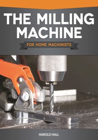
This book provides the detailed knowledge you need to successfully choose, install, and operate a milling machine in your home workshop. Heavily illustrated with color photographs and diagrams, understand which accessories are essential and which can be postponed until your activity demands it. The usage of each machine and accessory is explained in detail for the vast majority of applications in an active shop. Discover options for holding the many diverse shapes and sizes of work pieces that will inevitably surface during your machine's life. This critical task is by far the most important part of learning to use the machine. The Milling Machine will arm you with decision-making skills on which method is best for any application – whether to use a vice or an angle plate, mount the piece directly onto the worktable, or even produce a fixture specifically for the task. With the work piece set up and ready for machining, this book will show you the correct ways to cut metal and maintain all your milling tools.
Sie lesen das E-Book in den Legimi-Apps auf:
Seitenzahl: 195
Veröffentlichungsjahr: 2021
Das E-Book (TTS) können Sie hören im Abo „Legimi Premium” in Legimi-Apps auf:
Ähnliche


Parts of this book were updated for today’s American reader with regard to new techniques and tools. These updates were graciously provided by George Bulliss of The Home Shop Machinist, Machinist’s Workshop, and Digital Machinist magazines.
© 2013 by Harold Hall and Fox Chapel Publishing Company, Inc., East Petersburg, PA.
First published in the United Kingdom by Special Interest Model Books, 2011. First published in North America in 2013 by Fox Chapel Publishing, 1970 Broad Street, East Petersburg, PA 17520.
All rights reserved. No part of this publication may be reproduced, stored in a retrieval system, or transmitted, in any form or by any means, electronic, mechanical, photocopying, recording or otherwise, without prior permission of the copyright holder.
ISBN 9781565237698eISBN: 978-1-63741-093-6
Library of Congress Cataloging-in-Publication Data
Hall, Harold, 1933-
The milling machine for home machinists.
pages cm
Includes index.
ISBN 978-1-56523-769-8
1. Milling (Metal-work)--Amateurs’ manuals. I. Title.
TT209.H355 2013
671.3’5--dc23
2012042876
To learn more about the other great books from Fox Chapel Publishing, or to find a retailer near you, call toll-free 800-457-9112 or visit us at www.FoxChapelPublishing.com.
Note to Authors: We are always looking for talented authors to write new books. Please send a brief letter describing your idea to Acquisition Editor, 1970 Broad Street, East Petersburg, PA 17520.
CONTENTS
PREFACE
INTRODUCTION
CHOOSING
CHAPTER 1
THE MILLING MACHINE
CHAPTER 2
THE CUTTERS
CHAPTER 3
CUTTER HOLDING DEVICES
CHAPTER 4
METHODS FOR SECURING THE WORKPIECE
CHAPTER 5
OTHER ESSENTIAL ACCESSORIES
CHAPTER 6
OTHER ACCESSORIES
INSTALLATION
CHAPTER 7
INSTALLATION
USING
CHAPTER 8
GETTING STARTED
CHAPTER 9
USING THE VISE
CHAPTER 10
USING THE ANGLE PLATE
CHAPTER 11
USING THE WORKTABLE
CHAPTER 12
USING A DIVIDING HEAD
CHAPTER 13
USING THE ROTARY TABLE
CHAPTER 14
USING OTHER ACCESSORIES
CHAPTER 15
POSITIONING THE WORKPIECE
MACHINING
CHAPTER 16
MAKING THE FIRST CUT
FINALLY
CHAPTER 17
MAINTAINING YOUR CUTTERS
CHAPTER 18
FINAL COMMENTS
PREFACE
Having provided the book ‘Milling, A Complete Course’, Workshop Practice Series number 35, it became apparent that many workshop owners were looking for a more theoretical book on the subject rather than the hands-on approach of that published. This book therefore attempts to fill the gap, going into much greater detail regarding the choice of machine and the accessories that can be used with it.
There are chapters covering which accessories should be considered essential from the early stages and those which can be delayed until a need arises. This includes such accessories as dividing heads, rotary tables and boring heads. Within this detail, different versions of an accessory are discussed and their plus and minus points are examined.
The book then looks at the subject of installation, although this is relatively easy compared to the requirements for most lathes.
Having covered the subject regarding which machine and accessories to obtain, the following chapters discuss the methods of holding the workpiece, and in the case of active accessories (such as dividing heads and rotary tables) give sufficient detail regarding their use for all but the most complex applications.
Having the workpiece then ready for machining, the machining operation is covered in depth. The book concludes with a simple device for sharpening the end cutting edges of a high-speed steel end mill.
INTRODUCTION
For many years the milling machine was a rarity in the home workshop, with milling carried out on the lathe, some still using this as their only method. More cheaply available machines, though, and in a much larger range of types and sizes – particularly smaller ones – coupled I feel with greater wealth, has resulted them being much more common.
While some of this book will apply equally to both methods, it is mainly aimed at the workshop that possesses a conventional milling machine. I say ‘conventional’ although there are two types available: horizontal and vertical. Again, the horizontal machine is rare in the home workshop, so the book only deals with the vertical machine in depth.
Even having limited the choice to a vertical machine, there are still many decisions to be made – size, speed range, drive type, etc. All these considerations are discussed throughout the book.
While new machines are often supplied with a small number of accessories, these are rarely adequate, a major omission invariably being a cutter holding chuck. The accessories are therefore considered fully, from those that are essential, typically a cutter chuck, through to those that many will work without, such as a dividing head.
On the basis that an accessory is something that you may or may not need, then one item that is not an accessory, and one that cannot be done without, is a cutter. The range of these is vast, but mostly applicable to their use in industry. Even so, the number that may find a use in the home workshop is still quite large; which cutter to choose is, as a result, an essential part of equipping the workshop with a milling facility.
Having acquired your machine, together with the initial set of accessories, it will need installing. Fortunately this is simpler than with a lathe, but there are factors that must be taken into account; some are easily overlooked, such as whether there is enough headroom to remove the draw bar.
With the machine and all its accessories ready to be put through their paces, it is now that the real learning curve starts. The reason for this is the multitude of shapes and sizes of workpieces that will invariably surface during the machine’s life. After many years using a milling machine, you will still probably find yourself looking at something quite unlike any workpiece you have attempted previously. In simple terms, the decisions to be made are: do I use a vise or an angle plate or mount the workpiece directly onto the worktable, or perhaps even produce a fixture specifically for the task? Even then, how is the part positioned suitably for machining? This aspect of the milling machine is a major part of the book’s content, and for the machine owner the only way to gain the vital experience.
With the workpiece mounted and the chosen cutter in place, the next task is to start the machining operation. For this, such items as traverse direction, effect of the machine spindle not being at 90° to the machine table, speed and feed rates are covered.
The process of removing metal is not as simple as it may appear, but once the requirements are understood it will very quickly be mastered. However, choosing the method of mounting the workpiece and the order in which surfaces should be machined is a continuous learning process in view of the large number of workpiece shapes that will occur. Therefore, in terms of the time taken for machining a complete part, the process will typically be 40% deciding the method, 40% setting it up and only 20% actual machining – often even less machining time than that.
The various methods are therefore discussed in depth and illustrated by examples of actual set-ups. In a nutshell, therefore, the book works through choosing the machine and its accessories, mounting the workpiece using the chosen method of securing it, and finally machining the part. While this follows the actual workshop process, it is not easy to totally separate the use of the machine into these three sections, so do read the whole book before making any decisions regarding with what to equip the workshop.
CHAPTER 1
THE MILLING MACHINE
As stated in the introduction, there are two types of milling machine, horizontal and vertical, and this book will only consider the vertical type in detail as the horizontal machine is rarely found in the home workshop. However, briefly, horizontal types hold a cutter, like a very wide circular saw, on a horizontal arbor, and beyond that they work much like the vertical types. They are much less prominent in machine suppliers’ catalogs and those that do feature are well outside the budget of the vast majority of small workshops.
In the case of the vertical machine, though, the range available is very wide with a large number suitable for use in the home workshop. However, should the reader have a particular wish to include horizontal milling then a universal mill having both vertical and horizontal features, Photograph 1.1, is a possible approach. It should be apparent from the photograph that this has both horizontal and vertical spindles.
SIZE
When choosing a milling machine for the workshop, the main considerations will relate to the size of the workpiece that can be accommodated; this, however, is not easy as there are so many variations that fit into the equation. Of course, if you only have a very small workshop then the overall size of the machine may be the deciding factor and the tasks you attempt will then be limited by that. This is beyond what can easily be covered in this book, and it can only consider the space available for the part being machined together with the accessories used with it. These are typically a vise or angle plate and the cutter assembly fitted to the machine’s spindle. The three major dimensions are, therefore, table size (length and width), cutter spindle to rear column distance, and maximum table to machine spindle height.
Photograph 1.1 A universal mill with both vertical and horizontal spindles. (Chester)
Advising which size to purchase is impossible, but, having decided the type of work you intend to use the machine for, do tend towards machines that would appear rather bigger than required. In the vast majority of cases a large machine will adequately cope with small parts but obviously it will be difficult to stretch the limit of a machine that is just too small. Of course, if you are absolutely sure that you will only be using the machine for a specific interest, such as models in the very smallest scales, then perhaps you can choose a machine with very little capacity in hand.
Photograph 1.2 Do ensure that the accessories you choose are compatible with the machine. A 100mm vise on a machine with a 150mm wide table may sound suitable but, as the photograph shows, it is far too big.
A major factor in the decision is the size of the accessories that will be used, as it is important that, having chosen the machine and then the accessories, you do not find that the available space for the workpiece will be severely limited. The method has to be: make an initial choice of machine, then the accessories, consider the result and, if insufficient room is available for the workpiece, move up a size of machine or down a size in terms of the accessories.
This is not that easy, and you will need to know the overall size of the accessory and its fixing centers rather than just its capacity. Typically, a 100mm (4") vise on a table that is 150mm (6") wide would seem fine but, as Photograph 1.2 shows, it is far from the case; even without the swivel base it will not fit easily as it has no fixings allowing it to be mounted in line with the table. Also, the height of such a large vise will limit the space for the workpiece, which likewise needs to take into account the projection of the cutter chuck and cutter.
One item that needs a lot of headroom is the semi universal dividing head. If, therefore, this is to be an essential part of your workshop equipment, do take into account its height. Such considerations will be more critical if choosing one of the smaller machines.
SPEEDS AVAILABLE
Speed range is another factor, but again the purpose for which the machine is to be used is a major consideration. The reader will no doubt know that the larger the cutter the slower it should run, and vise versa. Obviously, therefore, if the purpose of the machine is for making large items of workshop equipment or models, then larger cutters, say 20mm (4") plus diameter, are likely to be used and quite slow speeds will be required. However, no matter how sizable your workpieces are, there will be occasions when very small cutters will have to be used, say 3mm (1/8") or even less. Because of this, a high speed should be available no matter how big the machine is. I would therefore aim for a speed range of at least 250 to 2000rpm. If you are purchasing a smaller machine and are unlikely to use cutters bigger than 12mm (1/2") then, 400–2000rpm would be acceptable.
Sketch 1.1 Showing how cutter speed varies with cutter size for a constant cutter surface speed. Based on a 12mm cutter running at 500rpm.
If, however, you anticipate using larger cutter diameters, such as a fly cutter or a large slitting saw, lower speeds would be advisable – 100rpm or lower if possible. Unfortunately, you are very much in the hands of the machines that suit your other requirements and a compromise in terms of speeds available may have to be made. I recommend that you aim for a top speed of at least 1500rpm so that small cutter sizes can be used. In practice you will find that larger cutters are much more tolerant of different speeds than are the very small sizes. This is best visualized by reference to the graph, Sketch 1.1, that shows, with a fixed surface speed at the outer diameter, how the speed has to vary with cutter diameter.
ELECTRONIC SPEED CONTROL
Some machines will use electronically controlled motors providing a stepless speed range, this being a considerable advantage in terms of convenience. However, excellent work has been performed for many years on machines having a very limited number of speeds available, so statements that suggest that the ability of providing exactly the correct speed is a major advantage should be given only limited credence. Avoiding the chore of belt changing is the real benefit, particularly as this can be quite difficult on some of the larger machines.
Frequently, the speed range quoted for this type of drive system is given typically as 0–2000rpm. It should be realized that at very low speeds the torque available will probably be insufficient and unable to perform any useful machining work, so it is worth making an enquiry as to the lowest useful speed. This statement needs clarification, however, as most often the torque output will be constant, being the same at low speed as at high speed.
To understand the problem it is necessary to compare it with belt or geared speed control. If we consider say a 1kw motor, and with the machine set up for top speed, then the power available will be 1kw resulting in a specific torque output. If now the mechanical drive is changed to reduce the speed to half the value, the motor will still be running at the same speed and again capable of producing 1kw of power. However, as the speed of the machine is now halved the torque available will have doubled, therefore as the speed is reduced further then the available torque will increase still further. This means that for a given sized motor there is a much greater torque available for using larger cutters and making heavier cuts.
Some machines partially overcome this situation by making machines with a combination of electronic and mechanical speed control, with the larger part of the speed range being achieved electronically but at some point down the speed range the speed is changed mechanically, this being done manually, allowing the motor to run faster than it would have done. Of course, changing the speed mechanically only needs doing if it is found that more torque is required and, as a result, the electronic control will be sufficient for most of the machining carried out.
Photograph 1.3 A typical round column mill drill. (Warco)
MACHINE VARIATIONS
Having decided that a vertical milling machine is the kind to obtain, there is still considerable variation within the type.
MILL DRILLS, ROUND COLUMN
Probably the most common machines in today’s workshops are mill drills, such as that shown in Photograph 1.3. These provide the X (left-right) and Y (towards-away) axes by the table’s movements but the Z (up-down) axis by traversing the cutter much like a basic drilling machine (the photograph should make this clear). While the head appears very like a drilling machine, it has three important additions as well as being more robust. The vital variations are that it has: (1) a fine down feed that is calibrated; (2) a down feed lock; and (3) a drawbar through the spindle to secure the cutter chuck. The reason for the need to secure the cutter chuck will be discussed later. I should add that the fine down feed can be disengaged and then operated as a conventional drilling machine.
Additional Z axis traverse is provided by moving the head up and down the round column. This can create a problem in some machining situations – the easiest, though least important, way of describing this is to consider it being used for drilling a large hole. First the position of the hole is started using a short center drill which is then replaced by a large much longer drill. It may be then that the head needs raising to allow the longer drill to be placed, and as the head is carried on a round column the head may rotate a little so that the alignment is lost. This can be a major problem when using the machine for milling if a change of cutter is needed and register between the already machined surfaces is lost. However, by carefully setting the height of the head for the first operation the potential problem can mostly be avoided and the problem will only surface very occasionally. This feature can on rare occasions become an advantage as the head can be swung enabling the cutter to reach the extreme areas of large workpieces.
What then are their advantages? Being economically priced is probably their main advantage, with them costing less than other types with a similar workpiece capacity. Similarly, they are bench mounted where other types of the same capacity would often be floor standing. Also, while I would not recommend using one as the workshop’s only drilling machine, due to the need to break from milling to perform a drilling task, their much more robust build would be useful when needing to drill large size holes. This especially applies if the workshop drilling machine is a light duty one.
Photograph 1.4 A small mill drill with dovetail slides for its vertical movement. (Chester)
MILL DRILLS, DOVETAIL SLIDE COLUMNS
These are very similar in principle to the round column mill drill, but having a rectangular column with a dovetail slide ensures that register is not lost when the head is raised. They are also made in a much wider range of sizes, with Photograph 1.4 showing one of the smallest and Photograph 1.5 a machine comparable with the average round column machine. For comparably sized machines they do tend to be rather more expensive, but some have the advantage of electronic speed control, or a geared head, while the round column machines are mostly belt driven.
Photograph 1.5 A large mill drill with dovetail slides for its vertical movement. It is fitted with CNC controls but could be purchased as a manual machine. (Arc Euro Trade)
Photograph 1.6 Turret mills have the facility of moving the table in all three axes but with the cutter spindle also capable of being traversed. (Warco)
TURRET MILLS
The only other form that is commonly available is one where all three axes (X, Y and Z) are provided with dovetail slides controlling the position of the table. The third axis (Z) is provided by a part of the machine called the knee. They do also have a head providing much the same features as a mill drill – that is, rapid down feed for drilling and fine down feed for setting the position of milling cutters (see Photograph 1.6 for an example). Machines of this type that are available are mostly for use in industry but that in the photograph, being among the smallest available, will be about twice the price of a similar capacity mill drill; even at that price, though, speed control is likely to be by belt changing. If you have the space and the finance, then they are to be given serious consideration as their advantages make them more pleasing to use.
SPINDLE BORE TAPER
Only two types of spindle bore are commonly available, Morse and R8. As an example, collets that fit these are shown in Photograph 1.7 – R8 top, Morse below. Morse is a shallow angle taper frequently used in home workshop machines and has a range of sizes, but only two, numbers 2 and 3, are common.
The R8 taper is a single size taper and is used in the very popular industrial Bridgeport milling machine but is now finding its way into smaller machines. Collets are made for this form of taper allowing cutters to be held without the need for a cutter chuck. A major benefit of this method is greater rigidity as it avoids the overhang of the chuck. Morse taper collets are also available that would provide the same benefits but seem to be less popular (no doubt due to the shallow taper which results in the draw bar needing a substantial hit to free the collet from its taper socket). With the R8 having a much wider angle, as can be seen in the photograph, the collet releases itself much more readily. There will be more about Morse and R8 collets later in the book.
The R8 taper will only be available on the larger mill drills and turret mills and then frequently as an option, Morse or R8. In this case, my recommendation would be to choose the R8 machine.
Photograph 1.7 Machines can be obtained with either R8 or Morse taper sockets in their spindles. The photograph shows collets for these: R8 top, Morse bottom. As can be seen, they are quite different.
Photograph 1.8 Some machines have heads that can be tilted.
PIVOTED HEADS
A few machines provide the facility to rotate the head, clockwise and anticlockwise, as viewed from the front, enabling the cutter or drill to approach the worktable at an angle (see Photograph 1.8). Do not be fooled into thinking that this will enable sloping surfaces to be easily machined; it will not unless the surface is narrower than the width of the cutter being used. Of course, if you use a fly cutter then wider areas can be surfaced, but their main use will be drilling holes at an angle.
Personally, I would attempt to find another method as getting the head accurately back into position for normal milling can be quite difficult. This will be covered in Chapter 7. Rather than pivot the head, some very small machines tilt the column at its base to achieve the same result, that in Photograph 1.4 being an example. I do not see the facility as a major benefit and it should be accepted as just being there if all other aspects of the machine suit your requirements.
TABLE STOPS
Adjustable stops that limit the movement of the table left and right (X axis) are omitted from some small machines, which is an unfortunate omission as they can be very useful, typically when milling a closed end slot. If two machines meet all your other requirements but only one is fitted with these stops, then go for this machine even if it is a little more expensive.


