Erhalten Sie Zugang zu diesem und mehr als 300000 Büchern ab EUR 5,99 monatlich.
- Herausgeber: Fox Chapel Publishing
- Kategorie: Lebensstil
- Sprache: Englisch
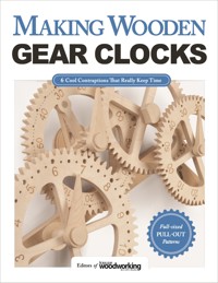
Making a piece of wood move is fun, but making it tell time is truly amazing! Inside this book, you'll find ingenious plans for creating awesome wooden machines that actually move and keep time. These working wooden wonders might just be the most enjoyable projects you ever build in your shop. Wooden gear clocks are not only fascinating to watch, but can be surprisingly accurate timepieces. Just don't expect atomic precision—after all, they're modeled on 17th-century technology! But as you build these scroll saw clocks you'll use all of the basic principles that still govern mechanical clocks today. Six well-illustrated step-by-step scroll saw projects are arranged by skill level from beginner to advanced, and full-sized scroll saw patterns are attached to the book in a handy pouch. With a little perseverance, you'll soon be ticking along happily with your own wooden clockworks. All you have to do is build them, wind them up, and let them run—no batteries required.
Sie lesen das E-Book in den Legimi-Apps auf:
Seitenzahl: 102
Veröffentlichungsjahr: 2016
Das E-Book (TTS) können Sie hören im Abo „Legimi Premium” in Legimi-Apps auf:
Ähnliche


© 2016 by Fox Chapel Publishing Company, Inc., East Petersburg, PA.
Making Wooden Gear Clocks is an original work first published in 2016 by Fox Chapel Publishing Company, Inc. Portions of this book were originally published in Scroll Saw Woodworking & Crafts magazine and Gizmos & Gadgets magazine. The projects and patterns contained herein are copyrighted by Fox Chapel Publishing and by the authors. Readers may make copies of these patterns for personal use. The patterns themselves, however, are not to be duplicated for resale or distribution under any circumstances. Any such copying is a violation of copyright law.
For a printable PDF of the patterns used in this book, please contact Fox Chapel Publishing at [email protected], quoting the ISBN and title of this book, as well as the pattern or patterns required.
Print ISBN: 9781565238893eISBN: 9781607658979
To learn more about the other great books from Fox Chapel Publishing, or to find a retailer near you, call toll-free 800-457-9112 or visit us at www.FoxChapelPublishing.com.
Note to Authors: We are always looking for talented authors to write new books. Please send a brief letter describing your idea to Acquisition Editor, 1970 Broad Street, East Petersburg, PA 17520.
Because working with wood and other materials inherently includes the risk of injury and damage, this book cannot guarantee that creating the projects in this book is safe for everyone. For this reason, this book is sold without warranties or guarantees of any kind, expressed or implied, and the publisher and the authors disclaim any liability for any injuries, losses, or damages caused in any way by the content of this book or the reader’s use of the tools needed to complete the projects presented here. The publisher and the authors urge all readers to thoroughly review each project and to understand the use of all tools before beginning any project.
TABLE OF CONTENTS
30-Hour Gear Clock
Genesis Wooden Gear Clock
Compact Gear Clock
Flying Pendulum Clock
Key-wound Gear Clock
Electromagnetic Gear Clock
Making a Gear Machine
Contributors
INTRODUCTION
Scroll Saw Woodworking and Crafts magazine is proud to present this collection of six of our best wooden gear clock projects and one of our favorite hand-powered gear machines. Though the gear machine can’t tell time, it’s still a really interesting and interactive project that will add to your home décor or make a great gift (if you can part with it).
Each project provides step-by-step instructions for cutting, finishing, and assembling your gear clock or machine. The patterns for each project are located in the pouch in the back of the book; we decided to put the patterns in a pouch so we could print them at 100% and make it really easy for you to get started right away!
There’s no doubt that each of these projects will challenge you—but if we know our readers (and we think we do) we know you’re up to it. Each contributor provided complete patterns, material lists, and instructions so woodworkers of any ability can find something to make. Whether you’re a woodworker, scroller, and maker or you just love to figure out how stuff works, you’re sure to find what you’re looking for in this book.
—The Editors
We suggest designating the patterns in the pouch as master copies and copying them to create the projects in this book. It's helpful to photocopy all of the patterns at once on the same machine. As you copy each pattern, check it against the master copy for accuracy.
30-Hour Gear Clock
Scroll a fully functional, 30-hour timepiece
By Marc Tovar
Once assembled, this wooden gear clock is an impressive work of art. When visitors discover that it runs without the aid of a battery and that you crafted it yourself, they will be truly amazed.
If you can bring yourself to part with it, the MLT-13 clock makes a wonderful gift for the individual who already owns just about everything. Don’t be surprised if the completed timepiece initiates a few custom commissions!
When cutting out the parts for the MLT- 13, it is very important that you make accurate cuts. This is especially true when you are cutting out the leaves of the pinions and the teeth of the wheels. If these are not cut accurately, the clock will not work. If you are not confident in your cutting ability, cut to the waste side of the lines and sand or file up to the lines.
If you follow my instructions and assemble it the way I did, the clock will run for 30 hours before you need to raise the weight again. Study the exploded drawing/assembly diagram and the patterns until you are familiar with them. The patterns will refer back to the exploded drawing for assembling the parts. All of the patterns are drafted with the pieces facing towards you. Material thicknesses are noted on the patterns. For a project this intricate that has so many delicate parts, use Baltic birch plywood for everything. The plywood will hold up much longer than hardwood teeth and leaves.
PREPARE THE PIECES
1Transfer the patterns to all of the blanks. Copy the pattern, apply spray adhesive to the back of the copies, and press them onto the wood. DO NOT use carbon or graphite paper. Accuracy is critically important.
2Drill the holes where indicated on the pattern. Use a brad-point drill bit. For the 9/64" (3.75mm)-diameter holes, drill first with a ⅛" (3mm)-diameter brad-point bit. Then, re-drill the hole with a 9/64" (3.75mm)-diameter bit (brad-point bits are not sized at 9/64" (3.75mm)).
3Cut out all of the pieces. Sand the pieces lightly to remove any rough edges.
4Apply the finish. Mix aniline dyes with denatured alcohol according to the dye manufacturer’s instructions. Dye the individual pieces following my example or choose your own colors. Apply several coats of shellac to all of the surfaces except on the teeth and leaves. Varnishes and shellacs create too much friction in the teeth and leaves, and your clock will have a difficult time running. You may want to wait to apply the shellac after individual pieces are glued together, but before assembly.
ASSEMBLE THE HANDS, WEIGHTS, AND AXLES
5Glue the collars onto the back side of the hands. Then, drill a ⅛" (3mm)-diameter hole between the hand and the collar into the axle hole for the set screw. At the same time, drill a ⅛" (3mm)-diameter hole between two leaves on the edge of all of the pinions. This is for inserting a drop or two of shellac to bind the pinion to the axle.
6Make three leather plugs for the hands. I punch them out from a leather belt using a piece of 5/32" (4mm)-diameter tubing. They will be inserted in the holes drilled in Step 5.
7Make the weight. Cut a 7" (178mm)-long piece of 1 ½" (38mm)-diameter thin-wall PVC pipe. Cut the wooden plugs for both ends, and sand them to fit tightly inside the pipe. Insert the bottom plug, and drill the holes for the ⅛" (3mm)-diameter pins through the pipe into the plug. Drive the pins into place. Thread the ⅛" (3mm)-diameter brass rod through the hole in the center of the bottom plug and fill the weight with #7 ½ lead shot. Put the top plug into place, with the brass rod threaded through the center hole, and drill the holes for the pins through the pipe into the plug. Then, drive the pins into place. Bend the ⅛" (3mm)-diameter brass rod to shape.
8Make the counter weight. Drill two holes into the ⅜" (10mm)-diameter dowel where indicated on the pattern. Then, taper the tip of the counterweight using a sander until it matches the pattern.
9Cut the pins, axles, and spacers to size. Use a hacksaw or a rotary power carver equipped with a carbide cutting disc. Remove any rough edges with a file and 400-grit wet/dry sandpaper. Use a small round file to remove any burrs from the inside of the spacer tubing. All of the axles need to be burnished. To burnish the axles, mount them into a drill, and lightly sand them with 400-grit wet/dry sandpaper. Glue the sandpaper to two sticks and use these sticks to squeeze the axle as it turns. Continue sanding until the axle has a high gloss and no longer grips the sticks.
ASSEMBLE THE CLOCK
10Assemble the frame. F1, F2, and the ribs make up the frame. The ribs are marked with numbers that are the same as on the dial of a clock. Glue and clamp ribs 12, 4, and 8 onto the F1 and F2 frames. After they dry, glue the rest of the ribs into their respective spots. With a ⅛" (3mm)-diameter bit, drill into the ends of the ribs, and dowel them to the frame. These dowels reinforce the strength of the frame. Drill small divets as hour markers where ribs do not join the two frames. Note: Rib 8 is attached to F2 only and does not require a dowel pin. Glue the wall anchor (WA) on the end of rib 12. Insert the ⅛" (3mm)-diameter anchor pins into ribs 4 and 8.
11Assemble the canon pinion (CP) and escape wheel (EW) mechanism. The CP has a 5/32" (4mm)-diameter bore for the brass tube that acts as both the arbor and the spacer between the CP and the EW. You must be able to insert the tube into the bore with hand pressure. It must be a snug fit. Glue the escape wheel pinion to the EW. The EW is mounted in the center of the clock. The CP is on the backside of F1. Insert the escape wheel arbor through the CP arbor, through the EW, the escape wheel pinion, EW spacer, and into the back frame. This will be a tight fit, and you may have to attach a hand drill to the tip of the arbor and screw it in through the EW.
12Add the clock hands and the hour wheel. The hour wheel has a 3⁄16” (5mm)-diameter brass tube as its axle. The hour hand is installed on this axle in front of the hour wheel. The hour wheel is installed in front of the frame and onto the CP tube. The minute hand is installed on the CP tube in front of the hour hand, and the second hand is installed on the EW axle. Be sure there is enough space between the hands to prevent them from touching each other. Lock the hands in place by screwing a ⅛" (3mm)-diameter set screw through the holes between the hand and collar until the leather plug grips the axle.
13Insert the clicker brass pins into the great wheel (GW). The pins will stick out the back of the GW. The clickers (C) are mounted onto these pins. The ratchet assembly is made up of R1, R2, R3, and R4. Look at the exploded drawing to see how the ratchet is assembled. Glue all of the pieces together. After the assembly has dried, bore out the center with a 9/64" (3.75mm)-diameter bit. Mount the GW and ratchet assembly onto the frame with a spacer between the ratchet assembly and F2. Install the hour wheel pinion on this axle in front of F1.
14Assemble the second wheel (2W) and the third wheel (3W). These wheels have the pinions glued in place on the front of the wheel. The 2W pinion has eight leaves, and the 3W pinion has seven leaves. The side view on the exploded drawing shows the spacers made from 5/32" (4mm)-diameter brass tubing that go on the axles. Note how the pallet axle has the spacers mounted on it. The other axles will be similar.
15Glue the pallets (P) and the pallet collar (PC) together. Drill a 3/32" (2.5mm)-diameter hole into the bottom of the collar for the crutch. Lay the 3/32" (2.5mm)-diameter brass rod on the crutch pattern and bend accordingly. Install the pallets onto the frame, and insert the crutch through the hole in the frame (F2) and into the pallet collar. This should be a tight fit. Add a few drops of shellac to secure the crutch in the pallet slot. At this time, go back and insert a couple of drops of shellac into the holes between the leaves of the pinions. This will adhere the pinions to the axles.


