Erhalten Sie Zugang zu diesem und mehr als 300000 Büchern ab EUR 5,99 monatlich.
- Herausgeber: Fox Chapel Publishing
- Kategorie: Lebensstil
- Sprache: Englisch
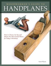
In a world of heavy and expensive handplanes, traditional wood handplanes are affordable, light in weight, low in friction, comfortable to use, and available in a wide variety of blade angles. Author and woodworking instructor Scott Wynn has been working with this versatile tool for four decades. In Traditional Wooden Handplanes he shows you how to make, modify, restore, and use antique planes. Scott reveals how traditional wood planes work, how to set up a flea market find, and how to tune up a new plane for peak performance. You'll learn about the different types and how to use them to their best advantage; which blade angles are best, which blade steel you might want to use, and finally, how to make your own set of planes using some modern techniques that simplify construction and improve performance.
Sie lesen das E-Book in den Legimi-Apps auf:
Seitenzahl: 314
Veröffentlichungsjahr: 2021
Das E-Book (TTS) können Sie hören im Abo „Legimi Premium” in Legimi-Apps auf:
Ähnliche


ACKNOWLEDGEMENTS
To my father, Jerry, who taught me always to watch and listen; and to my daughter, Josephine, who stands on her grandfather’s shoulders watching, listening, and learning—and teaching all of us.
I would also like to acknowledge the untiring support of Kathy Tam, the helpful guidance of technical editor Rick Mastelli, and the encouragement and long hours of Jerry Konicek, whose Woodworking Academy gave me the opportunity to verify and refine my techniques.
All illustrations by Scott Wynn
All photos by Rick Mastelli and Scott Wynn
© 2018 by Scott Wynn and Fox Chapel Publishing Company, Inc., 903 Square Street, Mount Joy, PA 17552.
Traditional Wooden Handplanes is an original work, first published in 2018 by Fox Chapel Publishing Company, Inc. Portions of this book appeared in Woodworker’s Guide to Handplanes by Scott Wynn. The drawings and illustrations contained herein are copyrighted by the author. Readers may make copies for personal use. The drawings and illustrations themselves, however, are not to be duplicated for resale or distribution under any circumstances. Any such copying is a violation of copyright law.
Print ISBN 978-1-56523-887-9
eISBN 978-1-60765-498-8
For a printable PDF of the patterns used in this book, please contact Fox Chapel Publishing at [email protected], stating the ISBN and title of the book in the subject line.
Library of Congress Cataloging-in-Publication Data
Names: Wynn, Scott, author.
Title: Traditional wooden handplanes / Scott Wynn.
Description: Mount Joy, PA : Fox Chapel Publishing, [2018] | Includes
bibliographical references and index.
Identifiers: LCCN 2017039965 | ISBN 9781565238879 (pbk.)
Subjects: LCSH: Planes (Hand tools) | Woodwork.
Classification: LCC TJ1201.P55 W95 2018 | DDC 621.9/12--dc23
LC record available at https://lccn.loc.gov/2017039965
To learn more about the other great books from Fox Chapel Publishing, or to find a retailer near you, call toll-free 800-457-9112 or visit us at www.FoxChapelPublishing.com.
We are always looking for talented authors. To submit an idea, please send a brief inquiry to [email protected].
Because working with wood and other materials inherently includes the risk of injury and damage, this book cannot guarantee that creating the projects in this book is safe for everyone. For this reason, this book is sold without warranties or guarantees of any kind, expressed or implied, and the publisher and the author disclaim any liability for any injuries, losses, or damages caused in any way by the content of this book or the reader’s use of the tools needed to complete the projects presented here. The publisher and the author urge all readers to thoroughly review each project and to understand the use of all tools before beginning any project.
CONTENTS
INTRODUCTION
CHAPTER 1: ANATOMY OF THE TRADITIONAL HANDPLANE
A SIMPLE DESIGN
THE BLADES
CHIPBREAKERS
Chipbreaker Variations
THE WEDGE
THE BLOCK
HANDLES
Anatomy of the Horned Plane
AND A WORD ABOUT CHINESE-STYLE PLANES...
Anatomy of a Chinese Plane
CHAPTER 2: SHARP
BLADE STEEL
BASIC BLADE CRITERIA
Steel Grain
Sharpening Versus Re-Sharpening
ANATOMY OF STEEL
The Ideal Edge
Disston Saws
Hardening, Tempering, and Annealing
TYPES OF EDGE STEEL
Alloy Ingredients
Forgeability
MY RECOMMENDATION
CHAPTER 3: HOW A PLANE WORKS
THE SIX TACTICS USED TO ACHIEVE BEST PERFORMANCE
1. THE ANGLE OF THE BLADE
Use the Lowest Effective Cutting Angle
Molding Planes
2. MOUTH OPENING
3. CHIPBREAKER
Hard Chipbreakers
4. BEVEL ANGLE
The Correct Bevel Angle
Honing a Hollow-Ground Bevel
How an Edge Dulls
Factory-Ground Blade Angles
5. SHAPE OF THE BLADE EDGE
Plane Geometry, a Summary
6. LENGTH OF PLANE/WIDTH OF BLADE
The Proportion of Length to Width
CHAPTER 4: TRADITIONAL USE: THE BENCH PLANES
JACK, JOINTER & SMOOTHER—AND A COUPLE MORE USEFUL PLANES
THE JACK PLANE
The Fore Plane
THE JOINTER PLANE
Trying, Long, and Jointer
The Correct Blade Shape
SMOOTHING PLANES
The Ideal Edge Shape
Chinese Smoothers
Why a Narrow Smoother?
A COUPLE MORE PLANES
DIMENSIONING STOCK
Winding Sticks
OTHER HANDPLANE PREPARATORY WORK
SHOOTING AN EDGE
Techniques for Shooting an Edge
CHAPTER 5: SHARPENING PLANE BLADES
A BASIC SKILL THAT LEADS TO OTHERS
BEVEL SHAPE
GRINDING
Grinding Out a Nick
Grinding on a Sanding Belt
SHARPENING STONES
Using and Maintaining Waterstones
Stone Choices
Listening
TECHNIQUE
Notes on Sharpness and Sharpening
Sharpening
CHAPTER 6: HOLDING THE WORK
OF SLAVES, DOGS, AND DEADMEN
A Simple Bench
CHAPTER 7: SETTING UP THE PLANES
AND TUNING THEM TO WORK TO THEIR FULLEST
SETTING UP A TRADITIONAL WOODEN PLANE
The Back of the Blade
Flattening the Back of a Plane Blade
Checking for a Custom Fit
Marking
What Really Happens
General Techniques for Adjusting the Plane Blade
Adjusting a Wedged, Tapered Blade
A Twisted Plane
The Oiler
Getting Rid of Those Burnishing Marks
Fitting a Sole Plate at the Mouth of a Plane
Setting Up a Flea Market Find
SETTING UP CHINESE PLANES
Check the Brass Mouth-piece
TROUBLESHOOTING
Efficient Planing
Keep Your Eyes on the Prize
Keep the Surface Flat
CHAPTER 8: MAKING & MODIFYING PLANES
EXPANDING YOUR OPTIONS
MAKING TRADITIONAL WOODEN-BODY PLANES
Handle Shape
Fitting a Moveable Sole Plate
Fitting a Moveable Sole Plate When Making a Krenov-Style Plane
INTRODUCTION
You may ask yourself: Why bother?
I mean, when we have so many other beautiful planes to choose from that could certainly do the job well enough? Planes we are probably more familiar with, marvelously mechanical metal planes of proven reliability. And other styles of planes as well, both beautiful and functional.
Well, simply put, if you’ve got a lot of work to do in solid hardwood, the traditional wood plane excels at efficiently working hardwoods and is better at this than any other style of plane.
Say you have a large plank, maybe a live edge board for a tabletop, and it’s too big to fit in your jointer. The traditional jack plane—maybe preceded by a scrub plane, used with the correct technique—is light, low in friction, comfortable in the hands, and will quickly take the high spots off, leveling one face of the board sufficiently to get good registration through the planer. Or maybe your planer isn’t big enough either. Traditional wood handplanes, used in the traditional sequence, with the blades correctly shaped and with appropriate blade angles, will make this job doable.
Or say you have a nice piece of figured hardwood that just wants to tear up when you go to work it. Only with a high-end two-drum sander will you get results that won’t take hours of sanding to get rid of the ripples, variations at changes in hardness, and streaking that the nonindustrial sanders tend to leave. Again, use of traditional wood handplanes, used in sequence with the correct blade shapes and angles—angles that you can’t find on most planes—will yield crisp, smooth results at a rate competitive with sanding—and without the dust and noise and vibration and sheet after sheet of sandpaper.
After over 40 years using handplanes, many times for hours at a stretch, days at a time, with every style of plane and in every type of wood, I have developed some criteria for planes for doing serious work on hardwood (I’m talking serious work here—not the occasional edge or snipe removal). You can of course challenge these if you wish, but it will give you something to think about—and maybe you can add a few criteria to your own list.
The criteria
Weight is an important consideration: you will be lifting these planes a lot during the day, maybe several hundred times. How often can you curl an 8-pound dumbbell (the weight of a premium #7 Bailey-type plane)? So, the planes should be comparatively light, though a balance between weight and inertia is often desirable.
The sole of the plane should be low in friction; like weight, the cumulative resistance adds up and it is palpably noticeable. It also interferes with feedback with how the plane is cutting.
You need blade angles other than just 45°. I have found that oak works tearout-free with a blade angle of 60° to 65°; walnut likes blade angles of 50° to 55° to finish. So the ideal plane should be available, or be able to be made, in a range of blade pitches; 40° to 65° is ideal, though 45° to 55° will suffice. This is for both reduced resistance when removing large amounts of stock (the low end of the scale) as well as the ability to reduce tearout for fine finishing (the high end of the scale).
Planes should be available in a variety of widths, with blades from 1 ¼" to 2¾" (3.2cm to 7cm) wide; this is because different planes do different tasks and require different width blades (much more on this in the succeeding chapters). In the same vein, you should be able to fit a variety of commonly available blades of different steels because different tasks and even different woods are done more effectively if the steel is matched to the work.
The grip of the plane must not be fatiguing, blistering, or bruising to the hands even after hours of pushing and must successfully transfer all the energy put into it to the cutting action. I have found that the larger the area of the hand the grip engages, the easier it is on the hand.
And, ideally, they should be affordable!
So how do the other styles of planes stack up when measured by these criteria? Let’s start with the Stanley Bailey style plane. If you have a lot of work to do you’ll soon realize these planes are heavier than their wooden cousins: often quite a bit. A traditional Razee-style wooden fore plane, for instance (of which plans and instructions for making are included in this book), is about 4 pounds, while the classic iron Stanley version is a smidgeon over 6 pounds. The premium version of the Bailey plane comes in at 7 ½ pounds (3.4kg)—nearly twice as heavy as its wooden counterpart! Arguments that planes of greater weight are needed to provide increased momentum to power through hardwoods (it’s not needed) have a flip side; they also require greater effort to overcome the inertia of getting the plane moving. Meanwhile you’re lifting twice the weight on every stroke of the plane. (Proper technique says you don’t drag the plane on the return stroke; this adds wear to the blade, though you will see a lot of well-known woodworkers do it. The plane should be lifted or slightly tilted on its side or front edge to reduce wear on the blade.)
The metal sole has a noticeably higher coefficient of friction with a noticeably higher resistance to the push. You can lubricate the sole but most lubricants, such as wax, wear off in a half dozen strokes and must be repeatedly reapplied.
The blade, with the exception of a couple of expensive high-end versions, is always bedded at 45°, which works ok for a number of woods, but not so good with a lot of common hardwoods; having blade angles that match the type of work to be done, and the type of wood to be planed, can save you a lot of time, effort, and frustration. Blade-width selection, however, is good, as is the variety of blade steels now available, allowing you to customize the type of steel to the kind or work and wood you want to do.
I do have a problem with the handles, however. I find they soon blister my hands. They’re too narrow, focusing the strain on narrow portions of the hand, and they’re often curved and/or angled wrong. I have a vintage #8 and a vintage #6, both with beautiful rosewood handles; the handle on the #6 fatigues while the other does not. They look the same; any difference is almost imperceptible. Others may not have experienced this, but I think if you’re doing significant work with these planes, eventually you will. The ball front knob is too small for doing a lot of work and concentrates the pressure on the center of the hand, which soon blisters, aided and abetted by the screw head in the center of it. The rear handle often allows the hand to slide down to its base and is angled and shaped such that the heel of the hand will start to get badly worn (and sometimes the side of the little finger). Between the weight, the friction, and the blistering handles, these planes are not made for extensive work. They can sit on the shelf for weeks at a time and be used off and on without readjustment or maintenance and they’re great for most of the tasks you’ll find around the wood shop, but they are just not the best choice for heavy work.
The Krenov-style plane, light, made of low friction wood, is a delightful smoother, but I don’t think it’s as versatile a style for all the jobs you might want to use a plane for. Because of the low position of the hand on the plane when making deep cuts to remove stock (as you might with a jack plane), the hand wants to slide forward against the blade. This takes its toll pretty quickly. Also, the selection of blades for this style of plane is limited. Those who favor Krenov-style planes might want to supplement their arsenal of planes with a traditional style jack, and maybe a jointer and scrub, depending on the type and size of work you do.
The Japanese-style plane is light, low friction, comes with some of the best blades you can get, and performs pretty well through most tasks, including stock removal—except when you have to remove a lot of stock in a hard wood. Surprisingly, despite no outward accommodation to the hand, they are not blistering, or even particularly fatiguing. But as a pull-plane, you do have to hold on to it; with a push-plane, if the grips are right, the plane is cradled in large parts of the hands so if you didn’t have to lift it to bring it back very little effort would be expended holding on to it. Additionally, with a push-plane it’s easier to get your body weight down and behind the push; this is more difficult when pulling a plane.
And finally, there is the issue of affordability. The traditional wood plane beats the competition here as you can often find usable vintage planes for a fraction of the cost of even a vintage Bailey—and often at one-tenth the cost of a new premium Bailey. A lot of these planes were made and a lot of them are still out there, and so far non-collectible user planes are still quite affordable. And you can get something on these planes that you can’t get on a new plane: a hand-forged laminated blade—often the best choice for smoothing (more on this later). While newly manufactured versions of the traditional wood plane may be as costly as a decent Bailey plane, they maintain the advantages of lower weight, low friction, good ergonomics while often having improved adjustment mechanisms, and the advantage over a vintage wood plane of not having to invest time to repair them before you can use them.
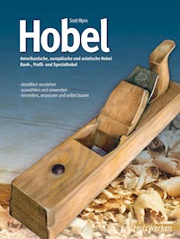
This book is about the traditional wood planes used predominantly in Europe and North America, both vintage and contemporary, and also will touch on the planes of China and Southeast Asia and how they might be useful. It will show you how all these traditional wood planes work, how to set up a flea-market find, as well as how to tune up a new plane to get the best performance out of it. It will talk about the different types and how to use them to their best advantage; which blade angles are best, which blade steel you might want to use, and finally, how to make your own set of planes using some modern techniques that simplify construction and improve performance.
CHAPTER1
ANATOMY OF THE TRADITIONAL HANDPLANE
A SIMPLE DESIGN
The anatomy of the traditional wooden handplane couldn’t be too much simpler, really, especially when compared to the number of sophisticated parts that the Stanley/Bailey plane uses to do the same job. Up until the 18th Century it consisted of just three parts: the blade, the block, and the wedge (only the Japanese plane is simpler with only two parts: a blade and a block). Bigger planes often had a handle, or “tote.” Sometime in the early 1700s the use of a chipbreaker became increasingly common, adding a fourth part.
On the left, a traditional jack plane with its wedged blade, a system in use for centuries. On the right a modern German horned jack plane, with a spring-loaded screw adjustment mechanism for adjusting the blade.
Figure 1-1. Wood Block Plane
THE BLADES
Unlike today’s planes, up until the early 20th century wood-body planes from Europe and North America usually had a tapered blade, thicker where the cutting edge is and thinning toward the opposite end. The main reason given for this is that the natural wedging action of a tapered blade resists being pushed back under the load of cutting wood, and also makes it easier to remove, because you can tap the blade down and it will release quite quickly (often too quickly). But it also makes it harder to adjust: if you adjust the blade down too far you may have to completely loosen the wedge and blade and start over if you want to readjust the blade back up.
I think the reasons usually given, such as this one, are the (questionable) side benefits of the method of manufacturing the blade. As we all know now—and they probably did then—parallel blades stay put just fine under the wedge. They are also easier to adjust because they do not lock in so tightly in one direction. You can move them down further than a fraction of an inch and not have to worry about them unexpectedly flying out of the mouth of the plane.
Here is my theory for the taper. When making a laminated blade by hand, you have the extra thickness of the edge steel added to the backing steel blade blank, the two of which must be forge-welded together. Then you have to hammer the assembly until the backing steel flushes with the edge steel on the top of the blade. If you do not hammer out the blade at the edge end as well—it is easier not to—then you have begun giving the blade a taper. From there, you continue the taper just making sure the back of the blade is slightly concave along its length. This guarantees the blade will bed properly at the heel despite any irregularities along its length, or irregularities in the hand-cut bed. This also means you can reduce the amount of grinding on the back. I have blades that still have the hammer marks on the back (Figure 1-2). A parallel blade must be accurately ground on both faces, which cannot easily be done freehand. An added benefit is you have maximized the thickness of the blade near the edge, further reducing the chances of chattering in use, especially if a substantial chipbreaker is added.
Modern versions of the traditional form have parallel blades and are only rarely laminated, though I do have a German scrub plane from the early 1980s that has a laminated blade. They were made and can be found (and laminated Japanese replacement blades for these planes are available), you just have to keep your eye out for them (for more on why you might want a laminated blade—and what it is, see the chapter on steel that starts here).
CHIPBREAKERS
Woodworkers throughout the world had for millennia worked with the same somewhat narrow selection of indigenous woods, often a single species, or no more than two or three, within a trade. They knew how the wood reacted, which tools and their setup worked best for those species, and they had a good selection of material and better control of their sources. New Worlds, new prosperity, greater travel and print exposure, brought a higher level of sophistication to their customers, which brought a demand for new designs and a higher degree of finish in the work. Additionally, new and imported woods often brought new challenges to providing this higher degree of finish than the indigenous woods they had worked with for centuries. The use of a chipbreaker helped solve some of these problems. It made planing these new woods more reliable, so the work went faster and with better results (see Figure 1-1).
Figure 1-2. If you look closely at this blade in the area of the chipbreaker screw, you can see the semicircular edges of the impressions left by the forging hammer.
CHIPBREAKER VARIATIONS
British and American chipbreakers have a slight difference (which has no effect on performance): British chipbreakers often have a “nut” of which there are a number of variations, that is proud of the top surface of the chipbreaker into which the screw is threaded; with an American chipbreaker the screw flushes out with top surface of the chipbreaker. This sometimes results in very little thread for that screw, depending of the thickness of the chipbreaker, but I haven’t had one strip out yet. (More about chipbreakers in Chapter 3here.)
The chipbreaker is almost always screwed to the blade, unlike Japanese planes and some Chinese planes. I say almostalways because I have a French smoother (smoothing plane) by Goldenberg that has a chipbreaker that is not screwed to the blade, but is adjusted independent of it. This is the only time I have ever seen this in a Western plane. This setup does increase the versatility of the plane because it makes it easier to adjust the chipbreaker up and down without having to disassemble the plane to unscrew the chipbreaker from the blade.
THE WEDGE
The most common form for the wedge in antique planes is similar to that shown in the illustration (Figure 1-1) with the center portion of the wedge cut out for chip clearance and wedgeshaped “ears” at the edges that wedge into matching abutments cut into the block. The cutout may be done in different ways: it may have a circular shape or as frequently found in Chinese planes, it may be a simple V-shape cut. Or there may be no cutout at all, the wedge cut to thin taper at its lower edge, though this is usually found on modern planes using a cross pin (Figure 1-3). Besides giving added chip clearance, the use of the ears simplifies fitting the wedge to the top of the chipbreaker, which may be curved or otherwise irregular.
Figure 1-3. The top two wedges are the most common type with “ears” that fit into tapered abutments either side of the plane, the center of the wedge relieved to a thin edge to clear chips. The third wedge from the top is from a French plane (with one of its ears slightly broken) and the bottom wedge is from a Chinese plane, though occasionally you might find similar wedges on European and American planes.
The use of a wedge fitted into abutments cut into the block, besides being a nuisance to fit simultaneously to an irregular chipbreaker and the taper in the block—and it must be well fit to eliminate chatter and prevent blade shift under use—is that seasonal movement or long term change in the block can change the angle of the wedge cut, preventing the wedge from fully tightening. You must then refit the wedge by careful trimming of (usually) the top of the wedge ears to exactly fit the block. This will lower the wedge a bit, which may require trimming the ends of the ears, and in a worse case, some refitting of the wedge to the chipbreaker. This usually doesn’t happen a lot in the life of the plane, especially if the block was dry when it was made and is oriented bark-side-down and quartersawn (or nearly so), but it’s something to keep your eye out for.
The use of a cross pin for bearing the wedge against is a solution that avoids the labor-intensive need to exactly cut the abutments and fit the wedge to them. But you won’t find this solution on any old planes. It starts showing up in early metal transition planes, but I don’t think I’ve seen it on an old wood plane. I think the reluctance to use a cross pin was because until the late 1800s drilling technology could not be counted on (at least in woodworking) to give an accurate and reliably-sized hole—and tradition imparts a certain inertia to changing a solution that has worked for centuries anyway.
A metal cross pin can be used when it bears against metal, such as on a Japanese plane where it bears on the chipbreaker (though it only holds the position of the chipbreaker and not the blade), and on some versions of Chinese planes where the chipbreaker doubles as a metal wedge; but a metal cross pin bearing against a wood wedge will soon damage the wedge, indenting it enough that adjustment becomes difficult. A wood cross pin can be used with a wood wedge, but the difficulty with a cross pin in general is its greatly reduced cross section often doesn’t provide enough resistance to keep the wedge from loosening when the plane is being used. A common response is to drive the wedge in tighter, but eventually this will damage the block, bend or break the pin, or leave an indentation on the wedge that makes adjustment difficult. German manufacturers solved these issues by using a metal cross pin with a wide flattened surface to grip the wedge, coupled with large diameter fixtures to which the cross pin is fixed to the block (See Figure 1-4). These cross pin mounting fixtures greatly increase the bearing area of the pin to the block, reducing the chance that an over-driven wedge will damage the block. An additional advantage to the system is that you can push or tap the wedge sideways to loosen it, rather than beating on the plane to loosen it. From personal experience this is a very successful solution to the wedge.
Figure 1-4. You can see the flattened cross pin under the wedge of this horned scrub plane.
James Krenov used a wooden cross pin to fix his blades, which he carved to a flat section where it engages the wedge to give it more bearing area. However, you have to glue the block up in sections in order to be able to insert it into the plane. What if you prefer—for a number of good reasons—to use a solid block? The solution is to add a wooden bearing plate to a wooden cross pin already drilled through the block (Figure 1-5). The wooden cross pin has a larger bearing area than a steel pin and is equal in hardness to the block, thus reducing stress and wear on the block, and the added bearing plate reduces the chance that the wedge will shift, and extends the pressure over a larger area of the wedge and blade, helping to reduce chatter. This is the system used in the planes described in the chapter “Making & Modifying Planes”see here.
Another wedging system in use is the screw-down lever cap (Figure 1-6). The lever cap is held to the plane with a screw inserted into the blade bed (rather than a cross pin), and much like the lever cap on a Stanley plane, the blade is adjusted by tapping, as with a wedge system. This can be a good system, and one that you might consider as a possible alternative for the cross pin/plate system used in Chapter 8. However, there are a couple things to look out for. First, the blade must be a parallel blade and not tapered. Second, because the blade will not move under full pressure, the lever cap cannot be tightened down fully until the blade is adjusted. However, because of the thinness of most modern blades and the curve of many chipbreakers over their length (to ensure tight contact with the blade), the chipbreaker/blade assembly is flexed to an arc when the chipbreaker is screwed to the blade.
Figure 1-5. Wooden cross pin with pressure fit bearing plate for fixing the wedge.
Tapping the blade to what appears to be its final position and then tightening down the lever cap flattens out the blade/ chipbreaker assembly, usually pushing the blade out of the throat slightly and changing the adjustment. You must then loosen the lever cap again, back the blade off, and second-guess how much the blade will move when the lever cap is tightened back down. This makes fine or frequent adjustments tedious. A thicker blade and/or a different chip breaker that keeps the assembly flat might remedy the situation.
Taking a quantum leap in development, a German manufacturer has replaced the wedge altogether with its Primus adjustment mechanism. The Primus blade-adjustment mechanism is one of the quickest and most precise adjustment systems. There is zero backlash on this adjuster. It can give precise adjustment on a smoothing plane, but I find it particularly useful on a jack plane, where frequent readjustment can be required to level a board; with this adjuster I can quickly and accurately readjust the blade as the board levels.
Its main drawback is its complexity. It is time-consuming to remove and replace the blade for sharpening, so frequent re-sharpening, as might be required for final finishing, is pure drudgery. To remove the blade for sharpening, first the blade-tensioning mechanism and blade adjustment must be backed off almost completely, and the blade withdrawn. Withdrawing the blade requires pushing the blade-tensioning mechanism back in and twisting and then pulling the tension rod out. Because the blade is now loose, it just flops around as you try to twist the T-bar on the end of the tension rod, because the T-bar gets wedged on the chipbreaker and must be worked off. Once the blade is out, two tight-fitting screws must be loosened to remove the chipbreaker (Figure 1-7).
After sharpening the blade, the chipbreaker must be repositioned and carefully tightened down with some trial and error (the use of another type of chipbreaker is not an option as both the blade-tensioning device and the lateral-adjustment mechanism are part of the chipbreaker assembly). Then you thread the T-bar on the end of the blade-tensioning screw through the hole in the chipbreaker, rotate it, push it forward, rotate again, and pull it back to its seat on the chipbreaker. This whole process of removing and reinstalling the blade can take 5 to 10 minutes (or seem like minutes). Doing it a lot gets to be quite irritating. Luckily, with its chrome-vanadium blade, if you are rough planing, you will not have to do it very often.
Over the years, other solutions to the wedge and how to adjust the blade have come about, especially with the German manufacturers, who are still one of the few manufacturers of traditional style wooden planes easily accessible to the American (and other) markets today. One type you might find is a version of the screw adjuster, with a knob similar to the Primus but working more like a Norris adjuster. It has the screw (a worm gear, actually) directly engaging threads on the chipbreaker. This version does not use a tension rod. Because the purpose of the tension rod is to eliminate backlash or play in the adjustment mechanism, this version does have some play, but it is not too bad and is a serviceable adjuster.
Figure 1-6. Horned Reform Smooth Plane with Screw-Down Lever CapThe body is pear with a lignum vitae sole. The body has had some extra rounding to accommodate the user’s hand.
Figure 1-7. The Interior of a Primus Jack PlaneIn the well of the plane you can see the two buttons that support the blade assembly at the top, and below that the T-rod that engages the chipbreaker and holds the blade assembly in the plane. The lateral adjustment is mounted to the chipbreaker. Two screws mount the chipbreaker to the blade.
Figure 1-8. This block plane by Goldenberg appears to give no accommodation to the hands.
Figure 1-9. A less common grip often used on small block planes, such as this Goldenberg plane, has the fingers of both hands bear on top of the plane in front of the blade, with the thumbs behind.
Figure 1-10. This coffin-shaped plane is typical of smoothing planes of the 1800s. This one dates probably to before the 1860s.
THE BLOCK
The basic block, or body of the traditional wood handplane has evolved into a few variations.
There is, of course, the basic block shape that is used for all the different types of these planes—jack, jointer, smoother—and on the larger versions, with an added handle or two. This shape may literally be a simple block with straight edges and sharp corners that appears to give no accommodation to the hands. I collected such a plane (the Goldenberg plane I mentioned earlier) because of its unusual blade and chipbreaker set-up, but also because its severe geometry seemed not just uncomfortable, but possibly damaging (Figure 1-8). It appears well used and taken care of, but it has all its straight rectangular corners intact, giving no suggestion of how you could push this plane—in the manner we are used to, like with a Stanley plane—without bruising your hands. This befuddled me. Then, just recently I saw (again) a video of the Swiss cooper Ruedi Kohler, filmed (coincidentally by Rick Mastelli, the technical editor and photographer of my first book) in 1992. In the film I noticed Herr Kohler used a series of hollowing planes to curve the inside of the staves. These planes were a plain block, not shaped, like the Goldenberg I had. But instead of using the planes one hand in front of the blade, the other behind, he gripped the planes on both sides, thumbs behind the blade and first fingers down flat on either side ahead of the blade. Mystery explained. This is very similar to the grip used for cross-handled Chinese and Southeast Asian planes. Without the cross handles it doesn’t seem to be a grip of great power like you might want in a jack plane to remove a lot of stock, but it provides sufficient power for smoothing and light shaving, especially in softer woods. The position also seems to give good control. It is most comfortable to use, however, when pushing straight ahead on short pieces; standing to one side as you might do when a piece is dogged onto the bench is more awkward with this symmetrical grip (Figure 1-9).
For smoothing planes that require more power, the coffin shape was developed (Figure 1-10). This configuration works pretty well for shorter smoothing planes, directing the energy efficiently forward and down, and giving wide distribution on the hand, even on the older planes that have not been particularly rounded off. The only real improvement I can see making here is to add a “thumbpiece” behind the blade to catch the crotch of the thumb and first finger; otherwise there is a tendency for the hand to ride up and chafe on the back of the blade.
Figure 1-11. Razee fore plane, 15" (38.1cm) longThe term Razee derives from the French vaisseau rase, a wooden warship with the upper deck cut away. Razee planes have the top of the body cut away behind the blade, lowering the handle and reducing the weight.
The Razee (from the French vaiseaurase, a wooden warship with the upper deck cut away) style of plane has the top of the body cut away behind the blade, lowering the handle and reducing the weight (Figure 1-11). These were often used to train students and apprentices because it was felt the full block versions were not only heavy (you have to remember these kids were 13 to 15 years old and mostly pretty small), but also easier to control than the full-block versions. This is because the high position of the handle on the jointer plane, while initially awkward, once mastered, gives greater feedback as to the angle of the plane to the work when shooting an edge. This is basic geometry: the further away you are from the face of the work the more exaggerated the tilt must become in order to maintain the same angle. Thus it makes it easier to tell when you’re going out of square.
I find the reduced weight of the Razee style useful for preparatory planes such as the jack and fore plane. I also find it useful for my panel plane (more on this to come), because not only is it lighter, the low position of the handle gives good feedback when smoothing.
HANDLES
Larger planes are fitted with handles or “totes.” These can be either open or closed, though functionally it makes little difference to the hand. The closed tote is perhaps a bit stronger, though if you’re pushing hard enough to break one of these handles, you’re working too hard! It may make it easier to pick up a larger plane for the return stroke as the larger planes almost always have a closed tote. The older planes are usually meant to be used with a three-finger grip, so they may be a little small for the modern hand or someone who prefers a full grip. Modern versions usually are larger and meant for a four-finger grip.
The larger planes also no longer have a front handle. Moxon depicts a bent-over curlicue of a handle that I could never figure out and have never seen an example of, even in a museum, but such a handle has not been used for at least 300 years, so it must not have been very effective. Occasionally, longer Scandinavian planes would be fitted with a horn or variation of the horn handle up front, similar to those they used on their shorter planes, but this is also uncommon now.
Figure 1-12. Horned Plane with a Lignum Vitae or Hornbeam Sole


